Pro-EC44 2-Loop Graphical Profile Controller & Recorder
Pro-EC44 Product Manual - 59540-2 September 2014
Page 16
Universal Input 1 Connections
Universal Input 1 is present on all models. This input is normally used for the measured
variable signal from a process to be controlled. It can be connected to thermocouples;
resistance temperature detectors; analogue mA; mV or V DC signals. The input settings are
in the Input 1 Configuration sub-menu. Connections for the various types are shown below.
Ensure that the signal is correctly connected, paying particular attention to the polarity.
Universal Input 1 Connections - Thermocouple (T/C)
Supported thermocouple types & ranges are listed in the input specifications section on page
245. Only use the correct thermocouple wire or compensating cable from the sensor to the
instrument terminals avoiding joints in the cable if possible. Where joints are made, special
thermocouple connectors must be used. Failure to use the correct wire type and connectors
will lead to inaccurate readings. Ensure correct polarity of the wires by cross-referencing the
colours with the thermocouple reference table above.
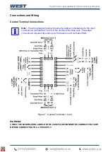
Figure 11.
Input 1 - Thermocouple Connections
Universal Input 1 Connections
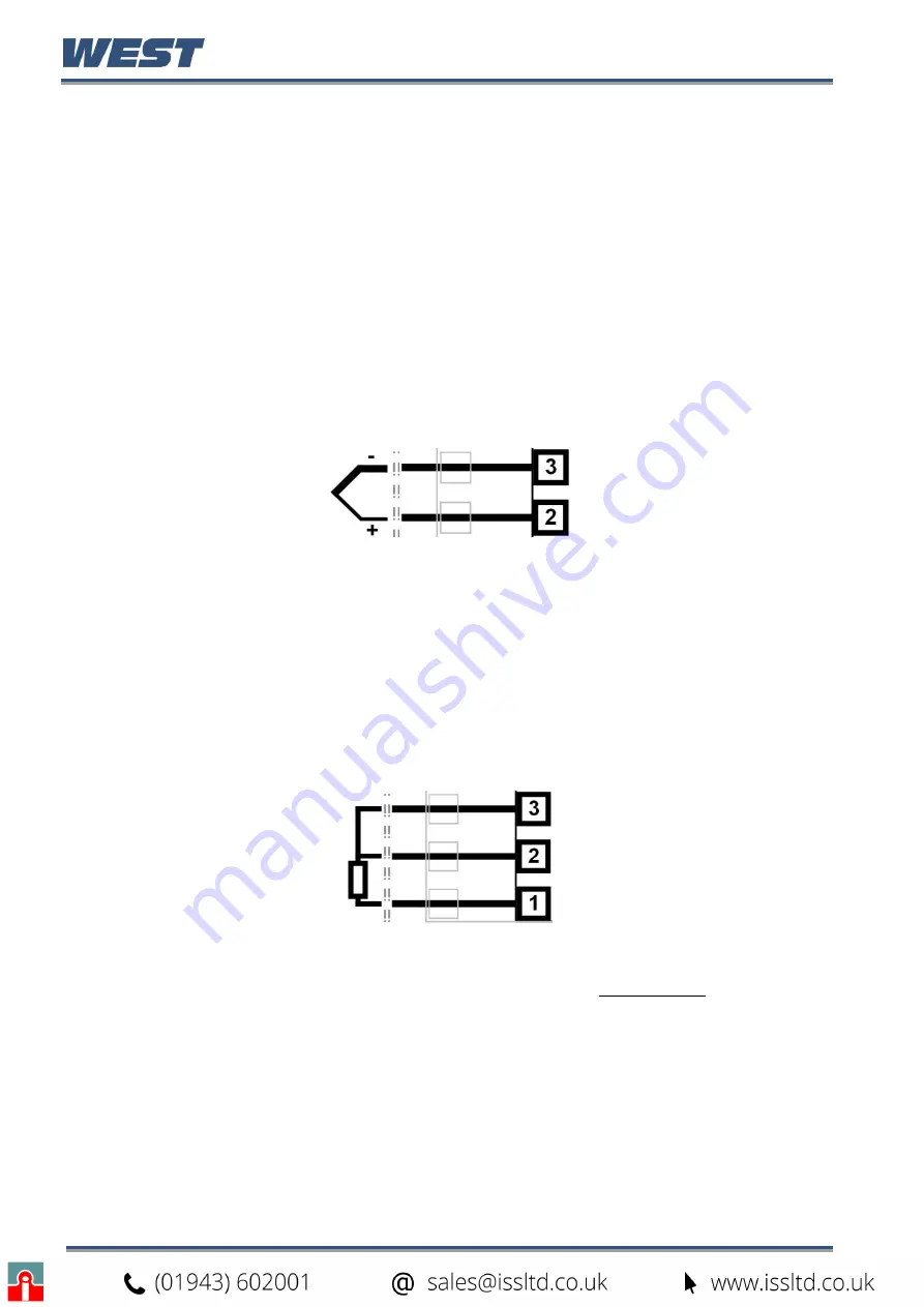
– PT100 / NI120 (RTD) input
The inputs supports two types of RTD. PT100 (platinum sensor, 1
00Ω at 0°C). For three wire
RTDs, connect the resistive leg and the common legs of the RTD as illustrated. For a two
wire RTD a wire link should be fitted across terminals 2 & 3 (in place of the third wire). Two
wire RTDs should only be used when the leads are less than 3 metres long. Avoid cable
joints.
Figure 12.
Input 1 - RTD Connections
Four wire RTDs can be used, provided that the fourth wire is left unconnected. This wire
should be cut short or tied back so that it cannot contact any of the terminals on the rear of
the instrument.
Summary of Contents for Pro-EC44
Page 1: ...Pro EC44 2 Loop Graphical Profile Controller Recorder Pro EC44 User Guide 59540 2 ...
Page 2: ......
Page 6: ......

