Pro-EC44 2-Loop Graphical Profile Controller & Recorder
Pro-EC44 Product Manual - 59540-2 September 2014
Page 51
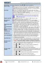
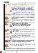
Set
n
– Integral
The integral time value (Automatic Reset) for PID Set
n
(
n
= up to 5).
Adjustable from 1s to 99min 59s or OFF
–
Only the set(s) in use shown.
Set
n
– Derivative
The derivative time value (Rate) for PID Set
n
(
n
= up to 5). Adjustable
from 1s to 99 min 59s or OFF
–
Only the set(s) in use are shown.
Set
n
– Overlap
The overlap (+ve) or deadband (-ve) between primary & secondary
proportional bands for PID Set
n
(
n
= up to 5). In display units
- limited to
20% of the combined primary & secondary prop band width.
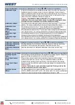
Set
n
– On/Off Diff
The on-off control hysteresis (deadband) for PID Set
n
(
n
= up to 5).
Adjustable from 1 to 300 display units, centred about the setpoint
–
Only
the set(s) in use are shown.
Set
n
- Breakpoint
The SP or PV value where the PID Set
n
(
n
= up to 5) if gain scheduling is
used. Set 1 is used from Scaled Input Lower Limit to the Set 2 Breakpoint,
then Set 2 used to the Set 3 Breakpoint etc. If a breakpoint is set to OFF
subsequent PID sets are not used. The final PID set runs to the Scaled
Input Upper Limit.
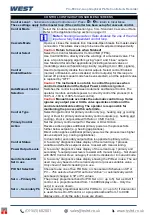
Manual Reset (Bias)
The Manual Reset value to bias the control working point within the
proportional band(s). Adjustable from 0 to 100% for single control or 100 to
+100% for dual control. Typically set to 80% of typical power needed for
setpoint, but lower values can help inhibit start-up overshoot.
Anti Wind-Up Limit
Adjusts the value
at which the “reset wind-up inhibit” is applied. Above this
power level further integral action is suspended. Adjustable from 10 to
100% of PID power. Lower values inhibit overshoot.
Caution:
If set too low control deviation can occur (the process
settles, but is offset above or below the setpoint). It this is observed,
increase the value until the deviation error is removed.
Ratio SFAC
The nominal ratio scaling factor used for Stoichiometric Ratio Control in
burner fuel/air control applications. Adjustable from 0.010 to 99.999.
– refer to the Ratio Control section on page 81
defined.
Ratio NO
A constant between 0.0 & 9999.0, added to the x1 (input 1) value in
Stoichiometric Ratio Control mode to allow for atomizing air when
calculating the process value. The total air flow is therefore x1 + NO.
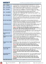
Primary Cycle Time
The primary power cycle time. Adjustable from 0.5 to 512 seconds. Applied
for time proportioned primary relay, SSR driver or triac control outputs
–
Not used for VMD Control modes.
Secondary Cycle
Time
The secondary power cycle time when dual control is used. Adjustable
from 0.5 to 512 seconds. Applied for time proportioned primary relay, SSR
driver or triac control outputs
–
Not used for VMD Control modes.
Primary Power Lower
Limit
The minimum primary output power limit. The control algorithm will not
allow the power output fall below this level. Adjustable from 0 to 90% but is
always at least 10% below the primary power upper limit.
Caution:
The instrument will not be able to control the process
correctly if the lower limit is above the level required to maintain
setpoint.
Primary Power Upper
Limit
The maximum primary output power limit. The control algorithm will not
allow the power output rise above this level. Adjustable from 10 to 100%
but is always at least 10% above the primary power lower limit.
Caution:
The instrument will not be able to control the process
correctly if the upper limit is below the level required to maintain
setpoint.
Summary of Contents for Pro-EC44
Page 1: ...Pro EC44 2 Loop Graphical Profile Controller Recorder Pro EC44 User Guide 59540 2 ...
Page 2: ......
Page 6: ......

