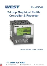
Pro-EC44 2-Loop Graphical Profile Controller & Recorder
Pro-EC44 Product Manual - 59540-2 September 2014
Page 9
4 Electrical Installation
CAUTION:
Installation should be only performed by technically competent
personnel. It is the responsibility of the installing engineer to ensure that
the configuration is safe. Local Regulations regarding electrical installation
& safety must be observed (e.g. US National Electrical Code (NEC) or
Canadian Electrical Code).
Avoiding EMC Problems
This controller has passed EMC compliance tests to EN61326. There should be no difficulty
achieving this level of compliance in use, but it should be borne in mind that the wiring of the
installation can significantly reduce the efficiency of instrumentation immunity due to the ease
with which high frequency RF can enter via unprotected cables.
The following general recommendations can reduce the possibility of EMC problems.
1. If the instrument is being installed in existing equipment, wiring in the area should be
checked to ensure that good wiring practices have been followed.
2. The controller should be mounted in a properly earthed metal cabinet. All round metal
shielding is important, so the cabinet door may require a conductive sealing strip.
3. It is good practice to ensure that the AC neutral is at or near ground (earth) potential.
A proper neutral will help ensure maximum performance from the instrument.
4. Consider using a separate isolation transformer to feed only the instrumentation. A
transformer can protect instruments from noise found on the AC power supply.
Cable Isolation & Protection
Four voltage levels of input and output wiring may be used with the unit:
1. Analogue inputs or outputs (for example thermocouple, RTD, VDC, mVDC or mADC)
2. Relays & Triac outputs
3. Digital Inputs & SSR Driver outputs
4. AC power
CAUTION:
The only wires that should run together are those of the same
category.
If any wires need to run parallel with any from another category, maintain a minimum space
of 150mm between them. If wires MUST cross each other, ensure they do so at 90 degrees
to minimise interference.
Keep signal cables as short as possible. If an earthed thermocouple is used or if the sensor
has a screened cable, it should be earthed at one point only, preferably at the sensor
location or cabinet entry point, by means of a metal gland. Ideally all analogue and digital
signals should be shielded like this, but for unscreened cables, large diameter ferrite sleeves
at the cabinet entry point are an effective method of reducing RF interference. Looping
cables through the ferrite sleeves a number of times improves the efficiency of the filtering.
For mains input cables the fitting a suitable mains filter can provide good results.
Summary of Contents for Pro-EC44
Page 1: ...Pro EC44 2 Loop Graphical Profile Controller Recorder Pro EC44 User Guide 59540 2 ...
Page 2: ......
Page 6: ......

