


PANEL DESCRIPTION
FRONT PANEL
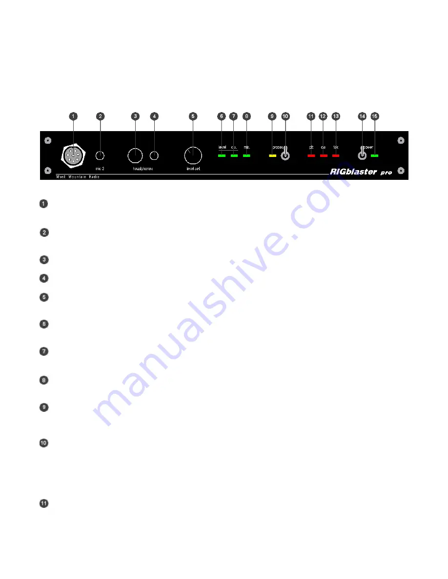
- MICROPHONE CONNECTOR, 8-Pin Screw-on Microphone Connector
– connects the radio microphone to
the
RIGblaster Pro
.
(May be used as mic out on a radio with an RJ45 microphone connector)
-
“mic 2”, an auxiliary mic connector for connecting a microphone with a 1/8 inch (3.5mm) connector. Main
mic does not need to be disconnected as this jack switches over automatically.
- COMPUTER MONITOR HEADPHONE JACK
– Accepts Headphones with a ¼ inch Jack
- COMPUTER MONITOR HEADPHONE JACK
– Accepts Headphones with a 1/8 inch (3.5mm) Jack
-
“level set” – For adjusting the audio level being fed from the PC audio Line Out or headphone out to the Mic
input of the attached radio in order to set transmit drive level.
-
“level” LED – A Green LED that indicates the presence of sound card audio in Receive Mode. In Transmit
mode, it indicates sufficient sound card audio to adequately modulate most radios.
-
“c.s.” LED – A Green LED, when on, indicates computer sound (c.s.) is being fed to the radio. When this
LED is on, the direct microphone path to the radio is disconnected.
-
“mic” LED – A Green LED, when on, indicates the microphone is available to the radio. See STEP 9
ADVANCED AUDIO PROCESSING CONSIDERATIONS later in this manual for more information.
-
“process” LED – A Yellow LED indicating that the
RIGblaster Pro
is in Process Mode This LED will turn on
only when the “Process Switch” is on and PTT is pressed on the attached mic or via an attached PTT
switch/foot switch or when PTT is activated by software through the serial port connection from the PC.
-
“process” Switch – Turns process mode on or off. Up is ON and down is OFF. This switch must be OFF
when the
RIGblaster Pro
is turned off for the mic to work normal.
If the “Process Switch” is OFF,
microphone audio is fed directly to the radio.
When the “Process Switch” is ON, mic audio can be
connected via the
RIGblaster Pro
to the PC mic input and back into the radio. Please see STEP 9
ADVANCED AUDIO PROCESSING CONSIDERATIONS later in this manual for more information about
Process Mode.
-
“ptt” LED – This Red LED indicates when PTT is activated the your mic, foot switch or by software through
the serial port connection from the computer.
Summary of Contents for RIGblaster Pro
Page 30: ......


