
The channel selector switch allows you to choose left, right, or both channels of your
sound card. You will usually get twice as much audio with the switch in the "both" position
because the channels are mixed together. You may use this switch to select the
appropriate channel when using software that processes receive signals on one channel
while transmitting on the other. The normal setting is "both".
The vox/auto switch selects the mode of PTT control and the audio switching. In the auto
mode the mic. is always connected normally and the computer audio is selected
automatically when the RIGblaster receives a PTT control command from the computer's
serial port. If the computer is transmitting you may override it by pushing the PTT switch
on your mic. and talking. In the VOX mode the computer audio is connected to work your
rig's VOX circuit. In the RIGblasters VOX mode you cannot use VOX, MOX or footswich
to activate your mic., only the mic. PTT button.
The "digital" LED shows green whenever the computers' audio is routed to your radio's
mic. jack. It turns green in the auto mode with serial control activation, or it is always on
when in the VOX position. Whenever you push the mic. PTT button it will go out indicating
that your mic is connected.
The power LED shows that 12 Vdc is applied. The RIGblaster has no on/off switch as the
power consumption is less than 0.2 watts in the auto position. It will run for about 60 years
for the price of a power switch. The RIGblaster has extensive power surge protection and
it is not necessary to turn it off.
We included your choice of 3M Bumpon protective feet or double sided adhesive pads.
You may want to stick the RIGblaster down, up or sideways with the pads.
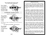
TROUBLESHOOTING
If you installed the RIGblaster following the steps in this manual you need not go back
to a previous step. The problem is isolated to the step that you found the problem on. Most
problems are software related and you need to consult your softwares' documentation.
If you would like further help, see our support page, for the latest help and
suggestions:
http://www.westmountainradio.com/support.htm
Please understand that the RIGblaster will not work if the software and computer does
not work. Make sure that you have your software operating properly before connecting
the RIGblaster and expecting it to work. You must read the documentation that comes
with the software! Sofware instructions are not included in this manual. We did not write
the software and we cannot support the software. The best thing to do if you have
software problems it to try an different software package. If you have problems with two
or more sound card programs you probably have a problem with you Windows sound
card software installation not your hardware.
Enjoy operating and work lots of DX!
Dan Gravereaux, N1ZZ and Del Schier, K1UHF
PAGE 6
PAGE 5
control. Set all of these controls so none of them are near all of the way up or down.
Remember that all of the adjustments are all cascaded (in series), and they all interact.
Transmit. Set your RF drive to maximum while adjusting the multiple audio level
adjustments for about 50% power. You should not exceed the AM, FM or RTTY power
ratings of your radio. After setting make sure you ALC meter is below maximum.
Note that if you run your sound card at maximum and the RIGblaster level turned way
down you will have distortion from your sound card and a poor quality signal.
VOX OPERATION
To set up for vox operation, instead of automatic serial control, you need to understand
the switching within the RIGblaster. In the auto mode your mic. is connected by default
and it will work normally with your radio's VOX. In the RIGblaster's VOX mode your mic.
is disconnected and your computer audio is hooked up. Therfore, your computer audio
may activate your rig's VOX circuit.
To set the VOX level controls you need to set all the levels as described previously. Turn
your rig's VOX on. Set the level, delay and anti-trip controls so that it works well with your
mic. The same settings should work with the computer since the computer audio should
be matched, almost exactly, to the same level as your voice from your mic.
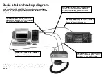
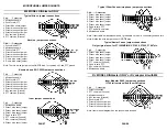
SWITCHES, CONNECTIONS, INDICATORS AND FEET
The back panel:
You will find a yellow DC power connector for the supplied AC adapter.
The RIGblaster needs approximately 12 Vdc. The center pin is positive. You may run
it directly from 10 to 16 Vdc but you need tp keep the grounding physically close to the
radio's mic circuit ground. This will avoid ground currents that may spoil your transmit
audio.
The DB25 serial connector is for two way PTT control from a standard modem cable
connected to a serial port.
The audio level adjustment potentiometer gives a great range of adjusment to match the
nominal output of the computer to your radio's mic. jack. Clockwise facing the back is
maximum audio level.
The audio input and outputs accept standard 1/8" stereo mini plugs. These jacks are
wired in paralell and the output may be used to monitor the audio from the computer that
is fed to the RIGblaster's input jack.
The Modular RJ45 jack accepts the supplied RIGblaster mic. cable that feeds the mic.
jack on your radio.
The Front panel:
The mic. jack varies according to the RIGblaster model; the M8 has
a standard 8-pin screw on jack, the M4 has a standard 4-pin screw on jack and the
RJ has a modular RJ45 8-wire jack. This is where you connect your mic.


