background image


Page 12 

System 

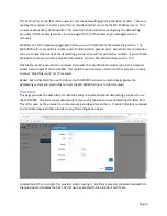
The System page is used for configuring and monitoring system level features of the MX-400 system.  

Settings 

This page provides a more comprehensive 
view into the system configuration of the 
MX-400SR. 

Network:  The network configuration is 
shown both here and on the front panel.  
Changes may be made on either UI.  Click 

on the gear 

 icon to configure any one 

of the four network ports.  

Server Certificate: Each datacasting server 
is uniquely identifiable and uses a 
certificate to sign all signaling data to 
prevent other services from masquarading 
as an MX-400SR datacasting server. i.e. 
Spoofing.  In most cases the certificate will be installed prior to shipment.  If no certificate is shown 
please contact West Pond technical support. 

FlexDM remote management:  West Pond’s 
remove management allows authorized 
personel to access the web UI of this, and 
other West Pond devices, via a cloud hosted 
web service.  If authorized, West Pond can also 
used this for support.  Communications for this 
feature utilize UDP port 1193 and TCP/IP port 
443 for communication.  All communications 
are between the device and the flexdm.net 
subnet.  If the MX-400SR has internet access 
and this feature is enabled, green check marks 
should exist on the Web UI next to Enabled, 

Registered, and Online.  If you wish to disable this feature, click on the gear 

 and select Enabled/No.  

The “Nonce” value is used during provisioning to identify this device and validate that it is in the hands 
of the owner.  For more information on creating a FlexDM remote management contact West Pond 
sales or technical support.  

Accounts 

There are three preconfigured accounts for managing the MX-400.  This page allows the administrator 
to set the passwords for these three accounts.  Use the User pulldown to select the user and then enter 

Summary of Contents for MX-400SR

Page 1: ...MX 400SR Installation Operations Manual Software Revision 1 4 2 West Pond Enterprises LLC 11 28 2017...

Page 2: ...ystem 5 Unpacking the unit 5 Installing in the rack 5 Making the connections 5 Power On 5 Configuring the system 5 Front panel 5 Accessing the WebUI 6 Getting familiar with the MX 400 7 Output 7 Fixed...

Page 3: ...West Pond for a copy of this specification Terms and terminology TS MPEG2 Transport Stream MPTS Multi program Transport Stream Inputs Physical inputs to the MX 400 Sources TS traffic entering the mul...

Page 4: ...w opportunities present themselves The MX 400SR is compatible with the MX 400IO Adaptive Bitrate Video Encoder the RR ST1000 receiver router and the IPDforPC datacasting application An SDK for creatin...

Page 5: ...ting providers These include file serialization forward error correction file carousels carousel priorities IP encapsulation encryption targeting key management TS capture pid filtering and more The d...

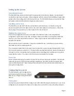
Page 6: ...tions vary with installation The ports are labelled for use Install these as you would any other data inserter or multiplexing device The F connector marked M1 is the monitor input Connect this to you...

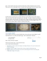
Page 7: ...through the video This can be done at any time and has no impact on the state of the system Accessing the WebUI Using a computer that shares a LAN with the MX 400 point a web browser to the IP address...

Page 8: ...providers are configured to do so PID Set the PID in hex that will be used to carry the datacasting signaling and ident packets Make sure this PID is not already in use on the transport This data is u...

Page 9: ...s to 0 NUL Bitrate Set this value to the minimum NUL packet bandwidth that should remain in the transport stream downstream of the MX 400SR This could be used to reserve bits for another purpose or si...

Page 10: ...ll the output maximum bitrate be exceeded nor will the output minimum NUL bitrate be undersubscribed Setting the Max Rate to 0 will block all lower priority providers from receiving more than their mi...

Page 11: ...tream and show the continued existence of datacasting content If the MX 400SR bypass is enabled the datacasting signaling will be removed from the transport and the monitor will begin scanning again O...

Page 12: ...e Port to be used for the RTP UDP packets Note all packets are RTP Interface Specify which Ethernet interface the RTP UDP stream will be bound Source Select ASI or RF as the source of the TS packets P...

Page 13: ...ent allows authorized personel to access the web UI of this and other West Pond devices via a cloud hosted web service If authorized West Pond can also used this for support Communications for this fe...

Page 14: ...his includes account information the output configuration and network settings It does not currently export the provider settings Use this feature to archive your settings and to clone devices for dis...

Page 15: ...the transport stream Bench test if required Once bench test is complete repeat steps 1 3 using station transport 4 Connect the RF and check the monitor page in the Web UI to see that the heartbeat was...

Reviews: