Page 10 of 24
PAM-190-P-A/I
3.3 Manual parameterization
3.3.1
Parameter overview
The manual adjustment is comparable with the adjustment via potentiometer. Not all parameters of the power
plug are available in this mode
1
.
Switch
position
Parameter
Setting range
Remark
0
DEFAULT
-
Released only by pressing the button "Up" and "DOWN"
simultaneously. Response: a short and fast flashing of
the LED.
1
CURRENT
0 | 1
0 = low current range; press „Button DOWN“
1 = high current range; press „Button UP“
2
MIN
0…60%
Deadband compensation
in relation to the current range
3
MAX
30…100%
Reduction in the maximum current
in relation to the current range
4
R:UP
50ms…5sec
Ramp time up
5
R:DOWN
50ms…5sec
Ramp time down
6
PWM
60…1500 Hz
PWM output frequency
7
-
No function
8
-
Current monitoring, no parameter input,
see LED defini-
tions.
9
-
Setpoint monitoring, no parameter input,
see LED defini-
tions.
3.3.2
Procedural method
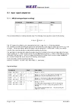
1. Press a button or turn the selector switch, which activates the manual adjustment mode.
The parameter-LED flashes.
2.
Select the desired parameter (1… 6) by the selector switch.
3. The parameter LED indicates - by flashing - the parameter mode.
a. At the lower boundary the LED lights only briefly
b. At the upper boundary the LED lights almost continuously
4. Press the UP or DOWN button.
a. A short activation of one of the buttons will change the parameter by a value of app. 1%.
b. A continual activation of one of the buttons will change the parameter continually (up to the
point where the upper or lower boundary is reached).
5. The parameters are stored automatically (app. 1 second after the last parameter adjustment). The
manual adjustment will be finished after 60 seconds.
1
The full functionality of the power plug is available via the PC interface only.


