background image

Section BXB-19D-20A

030-100689 Rev. A

R

10

1009IARA

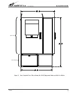
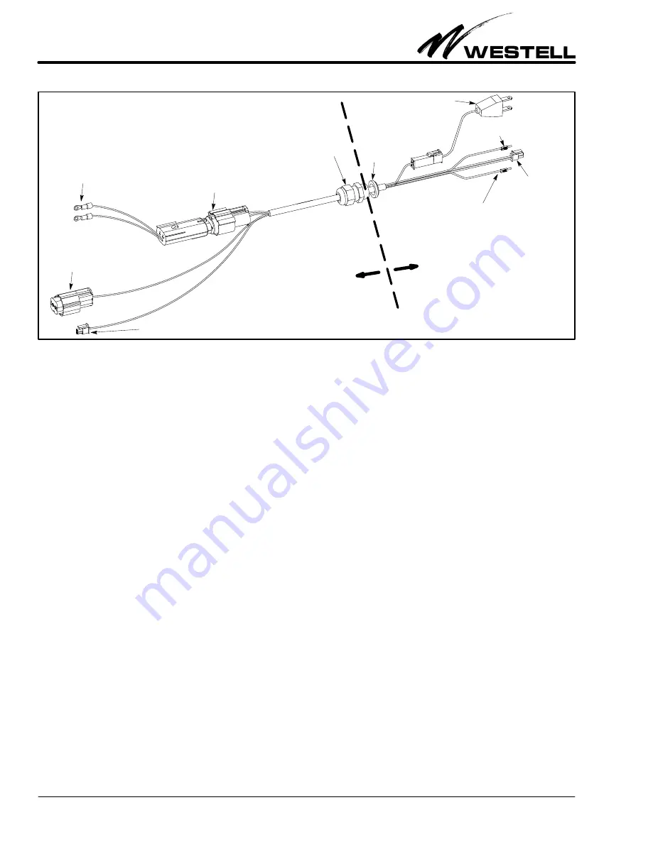
Figure 12. Battery Cable

AC plug

DC Power, Red, Positive lead

(to +V on battery charger)

DC Power, Black, Negative

lead (to -V on battery charger)

Lock nut

Waterproof  Grommet

(special plastic fitting

with threaded coupler)

Battery quick-

disconnect

Temperature

sensor probe

connector

Battery heater

pad connector

Temperature sensor probe connector

Battery ring

connectors

A

B

C

D

E

F

G

H

main Boxer cabinet

Battery End of Cable

to

Battery Compartment

Power End of Cable

to

time. If conduit is not required and only exposed cabling is
installed, rubber grommets can be used to seal the communica-
tions cabling in the cabinet.

3.8

Making Battery Compartment Connections

To make battery connections in the battery compartment, a
battery heater pad (optional), batteries, and battery cable must
be installed. The paragraphs below provide a description of
these procedures.

3.8.1

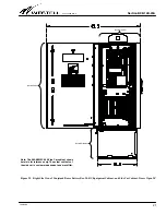
Installing the Heater Pad (optional)

An optional battery heater pad can be ordered and used with
the battery box. If used, unroll the heater pad. Place the heater
pad into the bottom of the battery compartment (Figure 13),
connector cable side up, and connector end on the right side of
the tray. Spread out the pad to cover the compartment floor.
Connect the heater pad’s connector to the battery cable (Con-
nector C in Figure 12) in Paragraph 3.8.2 after the battery cable
is installed.

3.8.2

Installing the Battery Cable

A special battery cable (Figure 12) is shipped with the battery
box, to facilitate backup battery connections. The battery
compartment end of this cable contains 4 connectors (shown as
connectors A, B, C, D in Figure 12), which are connected to the
batteries and the battery heater pad in the battery compart-
ment. The power end of the cable also contains 4 connectors
(shown as connectors E, F, G, and H in Figure 12), which are
connected to AC and DC power connectors in the main cabinet
above the battery box. The middle of the cable contains a spe-
cial grommet (fitting with a threaded coupler and lock nut)
which is installed in the hole at the bottom of the Boxer main
cabinet. Follow the steps below to connect the battery cable.

1.

Locate battery cable.

 Find the battery cable located inside

the kit of parts shipped with the battery box, and remove
it from its protective wrapping. Note the special water-
proof grommet and nut in the middle area of the cable.

2.

Remove knock-out in main Boxer cabinet.

 If not already

removed, locate the main cabinet’s bottom knock-out that
is provided for the battery cable and remove the knock-
out.

3.

Remove nut from battery cable’s middle grommet.

 Un-

screw and remove the lock nut from the threaded end of
the special grommet in the middle of the battery cable.

4.

Route power end of cable into the the main Boxer cabinet.

Starting inside the battery box battery compartment,
route the 

Power 

or 

main cabinet end

 of the cable (with the

E, F, G, and H power connectors) up through the previous-
ly removed grommet lock nut installed in the knock-out
hole in the cabinet, and into the main boxer cabinet. Pull
the battery cable up as far as it will go, until the special
grommet in the middle of the cable abuts the hole edges
and the threaded part protrudes into the main cabinet.

5.

Secure cable’s middle grommet in the knock-out hole.

Press and hold the cable’s special grommet against the
knock-out hole and screw the threaded lock nut back onto
the threaded part of the grommet. Fully tighten the nut.

6.

Install optional battery heater pad.

 Install the optional

battery heater pad, if ordered or equipped. Place the pad
on the battery compartment floor, with the cable/connec-
tor end facing to the right (it should abut the divider wall
between compartments).

7.

Connect heater pad to battery cable.

 Locate the connector

at the end of the heater pad cable and connect it to Con-
nector C of the battery cable.

Summary of Contents for A90-BXB19-D

Page 1: ... to at the side car cabinet 1 2 Document Status Whenever this practice is updated the reason will be stated in this paragraph 1 3 Product Purpose and Description The two compartment Boxer battery box is designed to be mounted with and under a Boxer 20 RU equipment cabinet and a Boxer Side Car cabinet see Figure 2 for an assembled installed but open view of the cabinets mounted on the battery box T...

Page 2: ...e Boxer cabinet mounted above it S Security and access via 216 tool or can wrench S Optional battery heater pad S Size 14 H x 34 5 W x 18 8 D S Weight less than 30 pounds Battery Compartment S Lockable yet detachable access panel S Louvered and screened side wall vents S Braided ground cable bonds panel to battery box S Kit of parts which contains the following items S Multi connector battery cabl...

Page 3: ... 2 3 Battery Spacer Block The battery box is provided with a sturdy rectangular battery spacer block that is designed to be used between the back wall of the compartment and the rear of the installed batteries to help insure a snug and square fit of smaller batteries placed in the compartment COMPARTMENT DIVIDER WALL NOTE Between the left side Battery Compartment and the right side Cable Access Co...

Page 4: ...e main cabinet above the battery box S installing all cable conduit or ductwork S making all ground power and signalling connections S mounting and wiring batteries inside the cabinet S testing the backup battery system S performing cabinet housekeeping and closing and lock ing the cabinet The following paragraphs provide detailed instructions for performing these procedures 3 1 Inspecting the Equ...

Page 5: ...hardware V Optional pad mount template A90 BXA 19PT2 V Concrete pad materials and equipment optional V Outdoor site preparation tools V Safety gloves and glasses optional V Power lift equipment optional V Appropriate ground wire and equipment Cable Preparation Tools and Equipment V Proper lengths sizes types and quantities of conduit connectors fittings and ductwork of choice V Proper lengths and ...

Page 6: ...knock outs in the right side wall of the equipment cabinet where the side car cabinet will attach to it 4 Set equipment cabinet on battery box Lift the Boxer equipment cabinet and place it on top of the battery box Slide the cabinet to align the five holes in the top surface of the battery box with the matching holes in the bottom of the equipment cabinet 5 Attach equipment cabinet to battery box ...

Page 7: ...r ductwork Dig and frame the pad location per company practice Once the pad is framed for concrete but before pouring gravel or con crete install any cable conduit or ductwork that is desired to be routed through the concrete and which will enter the battery box from the bottom 4 Prepare the pad for concrete add gravel Fill and com pact the pad site with gravel per company practice 5 Prepare and j...

Page 8: ... concrete being sure the anchors are fully im mersed and surrounded by wet concrete Remove any spilled con crete from the top of the template or from the bolts before it dries After concrete dries remove bolts When the concrete is cured remove the bolts If the insulating gasket is used shown in Step 1 place it on top of the template and be sure it does not cover the holes in the template below it ...

Page 9: ...d wire entrance hole as stated in the note below NOTE To improve the integrity of the cable entry seals when rubber grommets are used a water proof foam or silicone sealant should be used on the interior side of the cabinet around the ex posed grommet and cable entry Figure 11 Installing Battery Box Bond Strap Bolt Bond Strap Washer Large Ring End Large ring end of cabinet bond strap Rubber backed...

Page 10: ...n Figure 12 which are connected to AC and DC power connectors in the main cabinet above the battery box The middle of the cable contains a spe cial grommet fitting with a threaded coupler and lock nut which is installed in the hole at the bottom of the Boxer main cabinet Follow the steps below to connect the battery cable 1 Locate battery cable Find the battery cable located inside the kit of part...

Page 11: ...tery spacer block To help insure a snug battery fit install the optional battery spacer block if the batteries are small enough to accommodate the instal lation of all the batteries plus the spacer block The left wall tie down railing can be used to adjust the installation depth of this spacer block Orient the block as shown in Figure 13 and insert the left side flange of the block into the left w...

Page 12: ...er at the source before removing the battery cable 4 2 Inspection and Debris Removal Westellr Boxert battery box components are maintenance free however at least once every six months inspect Boxer to remove any debris from the vents or louvers Figure 14 This facilitates proper operation of the cabinet and battery box and allows unobstructed air flow 5 CUSTOMER TECHNICAL SERVICES 5 1 Customer Serv...

Page 13: ...XB19 D Westellr Boxert Battery Box for use with and mounting under a 20 RU Westell Box er cabinet and a Boxer side car cabinet Has knock out pattern that matches knock out hole pattern in the cabinets mounted above it Includes a battery spacing block and a kit of parts that includes a multi connector battery cable assembly 2 bond straps a battery tie down strap and a bag of hardware screws washers...

Page 14: ...Section BXB 19D 20A 030 100689 Rev A R 14 1009IARA Appendix A Product Views Figure 15 Front View of Battery Box 34 5 18 16 5 14 Figure 16 Right Side Boxer Battery Box 18 14 ...

Page 15: ...Section BXB 19D 20A 030 100689 Rev A R 15 1009IARA Figure 17 Top View Battery Box Figure 18 Bottom View Battery Box 1 8 diameter 1 place ...

Page 16: ...Section BXB 19D 20A 030 100689 Rev A R 16 1009IARA Figure 20 Concrete Pad Mount Template Dimensions Top View ...

Page 17: ...Section BXB 19D 20A 030 100689 Rev A R 17 1009IARA Figure 21 Front Conjoined View of Boxer Battery Box 20 RU Equipment Cabinet and Side Car Cabinet Boxer Battery Box Boxer Cabinet ...

Page 18: ...Section BXB 19D 20A 030 100689 Rev A R 18 1009IARA Figure 22 Front Conjoined View of Boxer Battery Box 20 RU Equipment Cabinet and Side Car Cabinet Doors Open 90_ Boxer Battery Box Boxer Cabinet ...

Page 19: ...ection BXB 19D 20A 030 100689 Rev A R 19 1009IARA Figure 23 Rear Conjoined View of Boxer Battery Box 20 RU Equipment Cabinet and Side Car Cabinet Boxer Battery Box Boxer Cabinet Rear Access Panel Removed ...

Page 20: ...Section BXB 19D 20A 030 100689 Rev A R 20 1009IARA Figure 24 Right Side View of Conjoined Boxer Battery Box 20 RU Equipment Cabinet and Side Car Cabinet Boxer Battery Box Boxer Side Car Cabinet ...

Page 21: ...Conjoined Boxer Battery Box 20 RU Equipment Cabinet and Side Car Cabinet Doors Open 90_ Boxer Battery Box Boxer Cabinet Note The A90 BXMSC 20A Side Car cabinet shown herein is for reference only The actual contents of the side car is customer dependent and may differ Boxer Side Car ...

Reviews: