
Section A90-DCP10X10
030-101868 Rev A
________________________________________________________________________________
Page 2 of 6
1509IARA
1
. GENERAL DESCRIPTION
1.1.
The Westell A90-DCP10X10 Breaker and Fuse Panel
provides distribution of DC power to equipment. The panel has 2
buses, each bus consisting of 10 pluggable fuse or breaker
positions. Alarm circuits are provided to indicate and extend
alarm conditions when faults occur.
1.2.
Input wiring is connected to high current, 2-hole lug input
terminals located at the rear of the panel. Each bus has its own
completely isolated inputs, allowing the distribution of two battery
voltages through the same panel.
1.3.
The power is distributed to the load side equipment
through breakers, TLS, TPS or TPC style fuses. There are 10
positions per group and two groups per panel. Each position is
available for installer connection at the rear of the panel. A
designation card is provided for keeping records of which position
is connected to which equipment and what amperage is to be
used.
1.4.
Alarm circuits are provided to alert service personnel of
fault conditions. A fuse alarm is generated when a fuse is blown
or a breaker has toggled into an alarm state. That is, a mid-trip
breaker alarms only in the tripped position and not in the off
position. However, a non mid-trip breaker will alarm when it is in
the off position. A red alarm LED
!
on the faceplate will
illuminate when a fuse or breaker alarm condition is present. As
well, the green Normal Operation LED
will extinguish to signal
a fuse/breaker alarm or input power failure and the appropriate
relay contacts will change states. These fuse/breaker panels
have common (C), normally open (NO) and normally closed (NC)
terminals for alarms. Note: the use of the alarm contacts is
optional. I
f you do not wish to extend the alarms, you don’t have
to do anything with the alarm pins. The “Normal” condition of the
relay exists when the panel is powered up without any fuse or
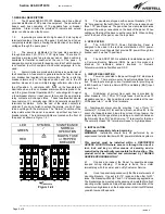
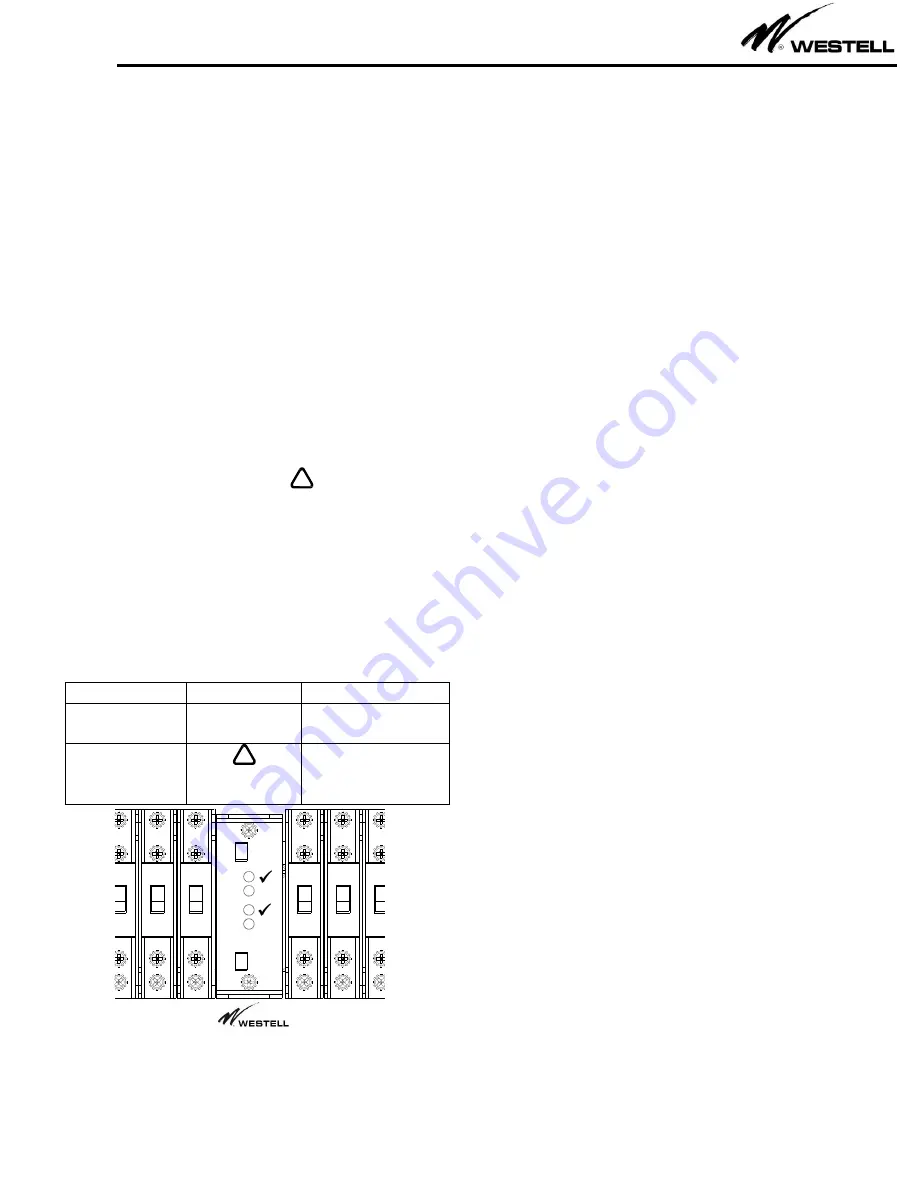
breaker alarms. The local alarm LEDs are located on the front of
the panel as shown in Figure 1.4.1.
LED
SYMBOL
SIGNIFICANCE
GREEN
NORMAL
OPERATION
RED
!
BLOWN FUSE
or TRIPPED
BREAKER
8
9
10
10
9
8
!
!
BUS A
BUS B
Figure 1.4.1
1.5.
The
panels are shipped with universal brackets (1” & 1-
1/4” hole spacing) that will fit both 19" and 23" wide racks and use
three 1.75" panel spaces. The panel has two clear plastic shields
to protect the wiring connections on the back of the panel. When
cabling out the top of the panel, use the rear shield. When cabling
out of the back of the panel, use the top shield.
2. APPLICATION
2.1.
The A90-DCP10X10 Power Distrirbution Panel is
designed to be used in the rack level distribution of DC power.
They are rack mount panels that provide DC power through two
busses; each bus has 10 positions.
2.2.
The A90-DCP10X10 is suitable for installation as part of
a Common Bonding Network (CBN). As well, this product is
intended
for
restricted
access
locations
in
Network
Telecommunications Facilities and OSP.
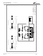
3. CIRCUIT DESCRIPTION
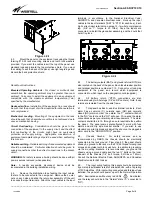
3.1.
Power is connected to the panel through 3/8” stud inputs
(see fig 4.4.1). There are two sets of input terminations for each
bus. These inputs are high current terminations for providing up
to 600A per bus. There is a Return (RTN) and Battery (BAT) input
for each bus.
3.2.
Distribution of current from each bus is provided by
either breakers, TLS, TPS or TPC style fuses. Each bus has 10
pluggable positions. Each position is made available at the rear
of the panel via ¼” on 5/8” stud terminals.
3.3. Fuse/breaker a
larm circuitry provides 1 set of form “C”
contacts (C, NO and NC) for each bus (Bus A, and Bus B). In the
event of a tripped breaker, blown fuse or loss of input power, the
proper relay will change states, providing a connection between
the Normally Open “NO” and Common “C” terminals for that bus.
The normally closed “NC” terminal will open to high impedance.
4.
INSTALLATION
Please read completely before beginning.
WARNING:
Installation should only be performed by an
experienced Installer familiar with DC power distribution systems.
This product must be installed within a RESTRICTED
ACCESS LOCATION where access is through the use of a
tool, lock and key or other means of security, and is
controlled by the authority responsible for the location. This
product must be installed and maintained by TRAINED
SERVICE PERSONNEL ONLY.
4.1.
Unpack and inspect the Panel for possible damage
incurred during shipping. If damage is found, file a claim
immediately with the carrier, and notify Customer Service.
4.2.
Once the panel is unpacked, verify that there are two sets of
mounting brackets. One set is for 19” racks, and the other for 23”
racks. The brackets will fit both 1
” and 1-1/4” hole spacing applications.
The brackets can be mounted so the panel can be installed for a flush
mounting or offset positions. Adjust the position and orientation of the
correct mounting brackets on the fuse panel, such that it will fit the rack
you wish to mount the panel in.


