

Section A90-DCP10X10
030-101868 Rev A
________________________________________________________________________________
Page 4 of 6
1509IARA
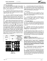
4.10.
If you wish to verify the fuse alarm circuit, you can insert
a blown fuse into one of the fuse positions. The red Fuse Alarm
LED
!
should light and the Normal Operation LED
should
extinguish and the appropriate alarm extension relay should
change states to extend the alarm.
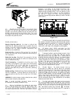
4.11.
Install panel output distribution fuses or breakers as
required. Be sure to size these protection devices to no more
than 80% of their rating (100A max for a 125A fuse, 80A max for
a 100A breaker). Fuses and breakers are not included with this
panel. Fuse ratings should be selected to match the load
equipment ratings. Once the appropriate fuses have been
selected, the fuse information for 1-10 on BUS A and 1-10 on
BUS B is to be recorded at the time of installation. Use the
provided designation card to keep a record of which equipment is
connected to which circuit and what
the fuse rating is. Be careful
not to overload the panel bus or BDB fuse position rating
supplying the panel.
5. SPECIFICATIONS
5.1. Voltage
±24 or ±48 V
DC
Typical
±22 to ±58 V
DC
Maximum
5.2. Breaker Size
0.1 to 100 Amps Max*
10,000 AIC, 80Vdc
(Sensata LML or LEL Series)
TFD Fuseholder
1-125A Max*
100,000 AIC, 170Vdc
(Littelfuse type TLS)
or
1-70A Max*
100,000 AIC, 170Vdc
(Telpower type TPS)
TPC Fuseholder
3-125A Max*
100,000 AIC, 80Vdc
(Telpower type TPC)
5.3. Current/Position
100 Amps Max**
5.4. Current/Bus
600 Amps Max**
Fuse at 750A Max
5.5. Current/Panel
1200 Amps Max
5.6 Output/Bus
10 Positions
5.7. Busses/Panel
2 Busses per Panel
5.8. Input Terminals
Two sets of Two 3/8” Studs
on 1” centers
Up to a 777MCM DLO cable
Max lug width = 1.54”
5.9. Output Terminals
Two ¼” studs on 5/8” centers
Up to a 1/0AWG, flex cable
Max lug width = 0.7”
5.10. Ground Terminal
Two ¼” studs on 5/8” centers
Up to a 2/0AWG cable
Max lug width is 0.85”
5.11. Alarm Block
0.045” sq wire wrap pin
5.12. Relay Current
1 Amp/58Vdc max
5.13. Dimensions
5¼ H, 17 W,7 D
(excluding brackets)
5.14. Rack Mounting
19” and 23” Racks
1” and 1.25” hole spacing for
WECO and EIA style racks
5.15. Weight
Approx 25 lbs
5.16. Operating Temp.
-40 to +70C (ambient)
(-40 to +158F)
5.17. Color
Off-white
5.18. Short Circuit
10,000A (Max)
Withstand Rating
*We recommend that you size breakers and fuses such that
they do not run at more than 80% of their rating. Thus a 125A
fuse should not be run at more than 100 A of continuous
current.
**The sum of the fuse/breaker currents must not exceed the
bus rating (600A) or the input fuse rating.
Compatible lugs for Input terminals
2 hole compression lugs for 3/8” studs on 1” centers (torque
20ft-lbs) example;
Panduit®
LCDXN750-38DF
777MCM, DLO, 90° lug
LCDXN750-38D
777MCM, DLO
LCD500-38D
500MCM, Code
LCDN500-38D
500MCM, Narrow tongue
LCD500-38DF
500MCM, 90° lug
LCDXN500-38D
500MCM, Flex, 90° lug
LCDX350-38D
350MCM, Flex
LCDXN350-38D
350MCM, Flex, Narrow
LCDX350-38DF
350MCM, Flex, 90° lug
The Panduit CT-930 (manual hydraulic) or CT2930 (lithium-
ion powered) crimping tools with the corresponding dies can
be used to crimp any of these lugs.
Compatible lugs for Output terminals
2 hole compression lugs for 1/4” studs on 5/8” centers
(torque 5.5ft-lbs) example;
Panduit®
LCD1-14A
1AWG, code
LCD1-14AF
1AWG, code, 90° lug
LCDX2-14A
2AWG, flex
LCDX2-14AF
2AWG, flex, 90° lug
LCDXN2-14A
2AWG, flex, narrow tongue
LCD2-14A
2AWG, code
LCD4-14A
4AWG, code
LCD6-14A
6AWG, code
LCD8-14A
8AWG, code
Burndy®
YAV25L2NT14FX
1/0AWG, flex, narrow tongue


