Section BXM‐05V‐20A
030‐101643 Rev. B
R
3
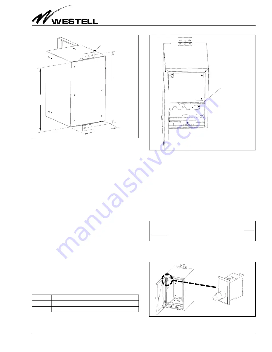
1205IARB
Figure 5.
Rear Isometric View
Mounting Bracket
25.18"
14" wide
23"
high
(between
mounting
holes)
tional security is available when a padlock is inserted through
the two holes in the protruding cylindrical lock wall: a padlock
hasp installed through the hole denies door tool access (tool
cannot reach the hex screw).
2.1.3
Front Door
A full‐size locking door provides maximum technician and
equipment access to the interior of the cabinet and also helps
protect the cabinet from tampering and vandalism. When the
cabinet is mounted and the door is open, the distance from the
back of the mounting brackets to the outer edge of the door's
lock flange is 29.11” (as shown in Figure 4). The door opens to
approximately 120 degrees. In the closed position, a gasket
installed around the inside perimeter of the door abuts the
front cabinet flange. When the door lock is tightened, the cab
inet's door flanges and gasket provide a weather‐tight seal to
protect all equipment installed inside the cabinet. The door
switch/sensor is described in Paragraph 2.2.1.
2.1.4
Mounting Brackets
Two mounting brackets are provided at the back wall of the
Boxer cabinet, one at the top and one at the bottom. Each
bracket has three mounting holes or slots. The center hole of
the top bracket is a keyhole, for easy one‐person, cabin
et‐self‐leveling mounting. Use mounting fasteners with a
diameter of up to
3
/
8
”). The vertical distance between the top
and bottom mounting bracket hole centers is 25.18” (see
Figure 5).
Quantity
Description
2
2.5” knock‐out for 2” conduit
6
1.125” knock‐out, for 3/4” conduit
Table 1. Knock‐out Sizes and Quantities
Figure 6.
Front View Showing Knock‐out Locations
Knock-outs on Floor
(2 large and 6 small
knock-outs)
2.1.5
Bottom Floor Knock‐outs
Multiple knock‐outs are provided on the floor of the cabinet.
The knock‐out sizes and quantities are shown in Table 1 and
Figure 15. Do not remove a knock‐out unless it is absolutely
necessary to do so for cable ingress and egress, and use either
tight‐fitting rubber grommets or liquid‐tight fittings, or other
proper and approved knock‐out hole sealants, to assure the
best internal air quality and weather‐resistance. Always use
proper and company‐approved tools to remove knock‐outs.
There are four, small, 0.300” diameter knock‐outs in the floor
of the Boxer cabinet where an optional battery box attaches to
the cabinet (hole patterns of both units match).
‐ KNOCK‐OUT REMOVAL NOTE ‐
Always remove knock‐outs where holes are desired before
mounting the cabinet or the optional battery box, regardless of
the type of knock‐out and the order of the mounting steps.
Figure 7.
Door Switch Location
Door Switch


