Section DSA-WM2-140-202
030-101674 Rev. A
R
9
0803I2RA
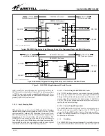
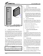
Figure 8. Optional 2555 Power Supply (Slot 15)
Front View
Optional Power Supply mounts
in Slot 15 of DSAWM-214.
Isometric View
ALM
PWR
2555I2
INPUT
115VAC
OUTPUT
48VDC, 2.0A
ISS.2
3.7
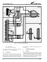
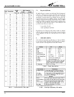
Customer Side/Interface Connections
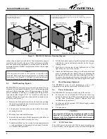
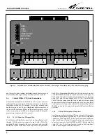
The versatile DSAWM-214 also offers two ways to make cus-
tomer side/interface connections: through the D-shaped,
25-pair, female RJ48H connectors (J15, J16) or through the 14
modular RJ48C jacks, labelled J1 through J14, located at the
bottom front of the enclosure for easy accessibility. Westell
provides jack inserts/covers for these jacks for protection when
connectors are not in use. Figure 5 and Figure 6 depict the con-
nector types and locations, and Table 3 lists the pin-outs and
pin designations for these connectors.
3.8
Module Installation
After the enclosure is installed and all wiring is complete, the
DNI/HDSL modules can be installed. Slots 1 through 14 of the
enclosure are dedicated 200-type slots. If 400-type modules are
used, the modules are inserted into odd-numbered slots, i.e., 1,
3, 5, 7, 9, 11, and 13. After inserting modules, mark and use the
circuit assignment card provided on the side of the enclosure
for easy future circuit identification. For module optioning,
and testing information, refer to the practice for each individu-
al module.
- CAUTION -
Use care when installing and removing modules -
do not force
a unit into place
. If a module resists insertion, remove it and
check for debris in or near the connectors and mounting
slots. The module may then be gently re-inserted.
4.
OPTIONS
4.1
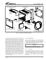
Telco Termination Module Options
Each DSAWM-214 enclosure is shipped with a
Telco Termina-
tion Module
(Figure 7) installed in the top horizontal slot. This
module can be used for wirewrap CO side connections and for
local DC powering. Also located on this module is the following
option.
S1 - This 2-position slide switch provides a shield ground from
TB1 connected to pins 7 and 8 of the RJ48C jacks, J1
through J14 with S1 in the THRU" position. The shield
ground wirewrap pins are permanently connected to the
TB1 SHIELD GROUND terminal pin. With S1 in the
OPEN" position, all the modular jack shield ground pins
are floating.
4.2
Enclosure/Model Options
The DSAWM-214 enclosure is a versatile and flexible enclo-
sure. Table 5 lists specific model numbers, options, and
ordering information for each model. Each model offers dif-
ferent features and equipment. Some of these differences are:
D
Two ways to make CO side connections
D
Two ways to make Customer side connections
D
Three ways to power the enclosure
D
Two types/sizes of modules housed in the enclosure
D
Several ways to mount the enclosure
5.
TESTING & TROUBLESHOOTING
5.1
Testing
After installation is complete, initial testing consists of per-
forming the procedures indicated in each practice for the
DNI/HDSL modules installed in the enclosure. An end-to-end
test should be performed to verify circuit operation. This pro-
cedure is intended only to ascertain proper span operation and
if problems should occur, to isolate the problems to the most
probable area.
5.2
Troubleshooting
If trouble is encountered, verify all installer connections to the
enclosure and check that the CO power or the enclosure fuse
is not blown. Also verify all module connections and option
switch settings, and verify the modules are making a positive
connection with the enclosure connector. If trouble persists,
replace the suspect unit and repeat procedures outlined. These
procedures are not designed to effect repairs or modifications.
Any tests beyond those outlined herein, or repairs made be-
yond replacing a faulty unit, are not recommended and may
void the warranty.
6.
CUSTOMER & TECHNICAL SERVICES
6.1
Customer Service & Technical Assistance
If technical or customer assistance is required, contact Westell
by calling or using one of the following options:


