background image

Section DSA-WM2-140-202

030-101674 Rev. A

R

3

0803I2RA

47

From LEC* (In)

To LEC* (Out)

From LEC* (In)

To LEC* (Out)

R

DSAWM-214 Enclosure

T

J1 - J14

R1

T1

(RCV)

(XMT)

J15

To CPE (Out)

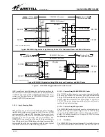
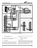
Figure 2.    DSAWM-214 Application and Circuit Overview

DSAWM-214 Enclosure

Facility/Network Interface

DSAWM-214 Enclosure

CPE/Customer Interface

P2

P1

(RCV)

(XMT)

5

15

J1 - J14

Optional DSAWM-214 Application Using 50-Pin Amphenol Connectors and RJ48C Jacks

From CPE (In)

To CPE (Out)

Typical DSAWM-214 Application Using Wirewrap Pins on 

Telco Termination Module

 and RJ48H Connector

* LEC = Local Exchange Carrier

* LEC = Local Exchange Carrier

55

49

1

2

5

4

(RCV)

(XMT)

Customer Side

From CPE (In)

Telco

Term.

Module

CO Side

CO Side

Customer Side

7

13

41

5

15

55

49

XMT

RCV

Module

T1

R1

T

R

Module

47

7

13

41

CPE  RCV

CPE XMT

FAC RCV

FAC XMT

CPE RCV

CPE XMT

FAC RCV

FAC XMT

T1

R1

T

R

R

T

R1

T1

Facility/Network Interface

CPE/Customer Interface

DSAWM-214 Enclosure

J16

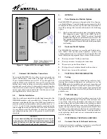
HRU modules are typically designed to use local power from the
48 V battery if it is available to the shelf. The only connections
to TB1, the power and ground terminal block, in this mode of op-
eration, are the chassis ground (CHASSIS GND) and circuit
ground (CKT GND) connections.

3.1.2.2

Local Powering Mode

When local power mode is selected, TB1 on the Telco Termina-
tion Module provides screw terminals for 48 V battery (-PWR
position) and 48 V return (+PWR position). A separate, fused,
48 V battery feed is required. The total enclosure input current
depends upon the mix, quantity, and size of modules. The
DSAWM-214 can accept up to fourteen 200-type modules or
four 400-type modules. While the specific input current will be
determined from the above particular variables, some typical
conditions are discussed in the following sentences.

3.1.2.3

Current Using 200-MECHANICS Cards

The T1 NIU module operates at a constant current typically
0.06 amps per module. An enclosure equipped with fourteen
200-type NIU modules will require 0.84 amps. This current will
remain virtually constant over the battery range of 42 VDC to
56 VDC. The power dissipation and heat release will vary di-
rectly with the battery voltage.

3.1.2.4

Current Using 400-type Cards

The HDSL HRU module typically operates at constant power,
therefore the input current is larger at the 42 VDC battery
range. A 400-type HRU with 6.5 watts of heat release will re-
quire 0.155 amps per module or 1.1 amps at -42 VDC for seven
modules in an enclosure.

3.1.3

Ventilation

The DSAWM-214 requires a minimum of three inches of open
space immediately above and below the enclosure, and also 1-2

Summary of Contents for DSAWM-214ALCI2

Page 1: ...Office CO side connections are made via wirewrap pins mounted on the plug in Telco Termination Mod ule located at the top of the enclosure or via two 50 pin Amphenol type connectors at the top rear of...

Page 2: ...ded that adequate horizontal and vertical space be left between multiple installations to allow for proper cable access and ven tilation The distance from the cable entry point should be consistent wi...

Page 3: ...nnections 3 1 2 2 Local Powering Mode When local power mode is selected TB1 on the Telco Termina tion Module provides screw terminals for 48 V battery PWR position and 48 V return PWR position A separ...

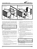
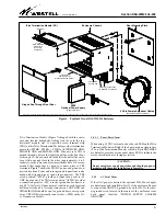
Page 4: ...ck plate from the enclosure by depressing the black metal push buttons located near the bottom on each side of the enclosure 2 Lift and place the back plate on the wall in the desired mounting locatio...

Page 5: ...om mended that spade lugs be used to connect wires to TB1 terminals Figure 7 shows the TB1 DC power and ground con nection locations Power and return ground connections can be made with stripped wire...

Page 6: ...but not factory installed for optional installation between the CHASSIS GND and CKT GND terminals on TB1 for applications re quiring chassis ground to be connected to circuit ground 3 5 2 Circuit Gro...

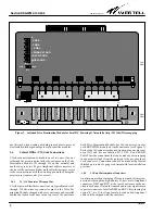
Page 7: ...de with stripped wire or by spade lug connectors TB1 screw position PWR is the battery return TB1 screw position CKT GND provides cir cuit ground as described in Paragraph 3 5 2 TB1 screw position CHA...

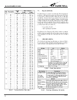
Page 8: ...access to these connections with the wirewrap pin method being the most secure requires a key for access 3 6 1 J1 J14 Connector Wirewrap Pins CO side network facility connections are typically made to...

Page 9: ...le is the following option S1 This 2 position slide switch provides a shield ground from TB1 connected to pins 7 and 8 of the RJ48C jacks J1 through J14 with S1 in the THRU position The shield ground...

Page 10: ...9 14 55 49 T R J16 Voice 800 377 8766 email global_support westell com For additional information about Westell visit the Westell World Wide Web site at http www Westell com 6 2 Part Numbers This equi...

Page 11: ...W O T1 41 4 R BR SGND 1 SGND 1 NC 2 NC 2 R 13 5 O W R 13 5 BR R T 7 6 W O T 7 6 R BR 3 R1 47 POS 3 3 G W 10 R1 47 POS 10 3 S R T1 41 4 W G T1 41 4 R S SGND 1 SGND 1 NC 2 NC 2 R 13 5 G W R 13 5 S R T 7...

Page 12: ...n the defective unit freight prepaid along with a brief problem description to the address we will provide to you when you contact us Voice 630 375 4211 email rgmdept westell com Replacements are ship...

Reviews: