_____________________________________________________________________________________
4
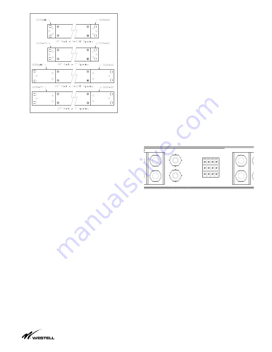
Mounting Options
Figure 4.2.1
4.3.
Mount the fuse panel in the required
position on the equipment rack using #12-24
thread forming rack mounting screws with
external tooth lock washers that are provided
with the panel.
WARNING:
For safety reasons all wiring
should be done with power source removed.
4.4.
Remove the distribution fuse or breaker
feeding the input cables that are to be
connected to the new panel. Note this panel
can handle a maximum of 125 Amps per
input. Please do not fuse/breaker the input
cables at more than 150 Amps each. Using
input cables specified by the Job Engineer,
hook up the battery input cables to the input
blocks on the back of the fuse panel (“BAT
IN” & “RTN IN” for each input). Each input
terminal uses a two hole compression lug
(1/4” on 5/8” centers, torque to 3 ft-lbs). See
Figure 4.5.1.
4.5.
Battery outputs (“BAT OUT” & “RTN
OUT”) for each fuse position are also
accessible through ¼” stud terminal blocks at
the rear of the panel. Each fuse position is
numbered on the face plate and that circuits
output is available at the back of the panel
with the same number. Note that each return
is isolated from the chassis frame and
isolated from all other returns. See Figure
3.1.1.
Note:
For this high current panel, a two hole
lug must be used on all stud blocks (input and
output, battery and return) for the fuse panel
to function properly.
4.6.
Each fuse position has a common (C),
normally open (NO) and normally closed (NC)
set of contacts for extending alarms. (See
figure 4.6.1 for the location and layout of the
alarm relay contacts). Wire wrap the alarm
connections as per your alarm systems
requirements. For example; to achieve a
“ground alarm extension”, connect a ground
supply to the common (C) contact and
connect the alarm signal wire to the normally
open (NO) contact. In an alarm state a
“ground” will be sent out from the panel.
COM
NC
NO
1
2
3
4
CHASSIS
GND
BAT IN
BAT OUT
ALARMS
Figure 4.6.1
Note:
To protect the alarm wiring and
circuitry, the current will be limited through the
alarm contacts to 1A by a self-resetting over
current device (1Amp P.T.C.). See the
attached schematic (drawing 1009-10).
4.7
Chassis Grounding; for safety reasons,
the chassis should be electrically connected
to the rack ground. From step 4.3, the panel
should already be bonded to the rack via the
#12-24 thread forming rack screws and
outside tooth lock washers used to pierce the
paint (this hardware must be used to pierce
paint on the panel and the rack). In addition
to grounding via the mounting brackets, it is
recommended that the chassis be further
grounded using a separate ground bonding


