Equipment Issue A
030-101705 Rev. C, August 2009
Section VEU-E30-20A
R
Copyright
E
2009 Westell, Inc. All rights reserved. Westell
r
and VirtualEdge
r
are registered trademarks of Westell, Inc.
LGX
r
is a registered trademark of Furukawa Electric North America, Inc.
Nylatch
r
is a registered trademark of Hartwell-Dzus, Inc.
0908IARC
VirtualEdge
r
VEUE-30 12-Port Wall-mount Universal Enclosure
CONTENTS
PAGE #
1. GENERAL
. . . . . . . . . . . . . . . . . . . . . . . . . . . . . . . . . . . .
2. INSTALLATION
. . . . . . . . . . . . . . . . . . . . . . . . . . . . . . .
3. CUSTOMER & TECHNICAL SERVICES
. . . . . . . . .
4. WARRANTY & REPAIRS
. . . . . . . . . . . . . . . . . . . . . . .
5. SPECIFICATIONS
. . . . . . . . . . . . . . . . . . . . . . . . . . . . .
1.
GENERAL
1.1
Document Purpose
This document describes Westell’s VirtualEdge
r
VEUE-30 se-
cure-access, 12-port, wall-mount universal enclosure designed
for flexible services hand-off to subscribers. The VEUE-30 is
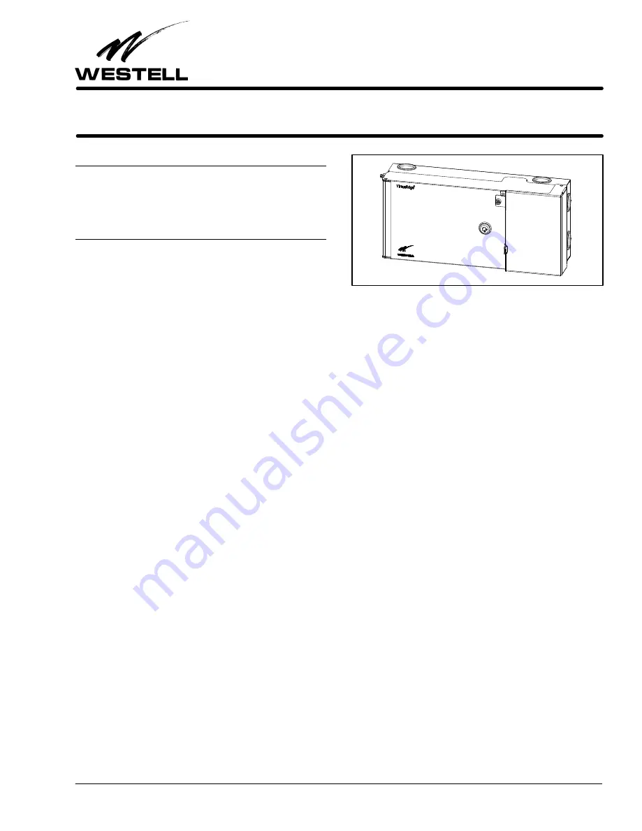
shown in Figure 1.
1.2
Document Status
When this practice is updated, the reason will be stated here.
Revision B added optional splice trays. Revision C updates
Table 1.
1.3
Product Purpose and Description
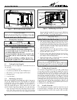
The VEUE-30 VirtualEdge Universal Enclosure (VEUE) is a
wall-mountable, compact, two-door, secure-access universal
enclosure that serves as an interface for an ethernet hand-off
point by the Telco to terminate any 10Base-T, 100Base-T,
Cat5E, fiber, or Coax services (or a combination thereof), typi-
cally at the CPE point of demarcation. The service terminated
is determined by the coupler type used inside the enclosure,
and the enclosure accommodates up to 12 field-provided cou-
plers that can be installed in one of three, detachable,
4-position, LGX
r
-type panels. Cable access to either the pad-
lockable Customer side of the enclosure or the key-lockable
Network side is made through either top, bottom, or side-wall
rubber grommets. Also on the Network side is a two-piece
spool for fiber cable storage (removable if space is a concern).
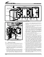
A removable divider wall between the compartments doubles
as a mounting plate for the three LGX-type panels.
To enable a greater variety of service and interface offerings, ser-
vice providers are putting more fiber into customer premises, via
either Fiber-to-the-Premise or placing more fiber multiplexers
and IP aggregation devices closer to subscribers. In business
markets, the strong demand for Transparent LAN and Virtual
Private Network services, where the customer’s LAN is ex-
tended over the Service Provider Network to provide native
Ethernet service, creates numerous applications for Westell’s
VirtualEdge Enclosures.
1.4
Product Mounting
The VEUE-30 is typically mounted to a wall or equipment
backboard at the customer premises hand-off point.
1.5
Product Features
The VEUE-30 offers the following features.
Figure 1.
VEUE-30 Wall-mount Enclosure
S
Separate access for Network and subscriber
S
Secure access demarcation
S
Hinged, key-locking, Network door allows full access for
Network-side technicians
S
Network-side two-piece spool for surplus fiber cable
S
Interior fiber containment lips for fiber management
S
Interior, slide-out, compartment divider wall with 3 de-
tachable LGX-type panels facilitates access to and
connections for both Network and Customer sides
S
12 empty coupler positions for flexible hand-off (fiber,
DS3, Ethernet)
S
Accepts two splice trays (up to 24 splices)
S
Smaller, hinged, padlockable and screw-locking front
door for Customer side access
S
Cable access via eight rubber grommets
S
Predrilled, keyhole-shaped, mounting holes in rear wall
S
Cable tie-downs on enclosure’s back wall
S
Wing-nut clamp to secure fiber cable strength members
S
Ground lug
S
Transparent LAN Services
S
10/100M Ethernet Services
S
GigE Optical hand-off
S
Optional LGX-type panels available (one with 6 SC cou-
plers, one with 6 BNC couplers)
2.
INSTALLATION
Installation consists of inspecting the equipment for damages,
following proper safety precautions, gathering the required
tools and equipment, determining the mounting location,
mounting the enclosure, and making the appropriate ground-
ing, power, and wiring connections. The following paragraphs
provide detailed instructions for performing these procedures.


