Section VEU-E30-20A
030-101705 Rev. C
R
4
0908IARC
11. Insert all Network cables (or pigtails) into their proper cou-
plers on the Network side of the compartment divider wall.
12. If no Customer connections are to be made at this time, secure
the divider wall by tightening the two locking screws.
13. After all connections are made, secure/lock the large exterior
Network door.
2.4.2
Making Customer Interface Connections
The Customer wiring and termination connections are made in
the right-side compartment of the enclosure.
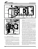
1.
Open the Customer-side door (see Figure 2) by unscrewing
the two screws and removing any optional padlock.
2.
Using any of cable access holes, with a sharp object or knife
carefully cut one or two slits through the rubber grommet pro-
vided in the cable access hole. Make the slit just large enough
to allow the wires and cables to fit through the grommet.
3.
Route all Customer wires or cables through the grommet.
4.
Attach or secure each Customer’s cable plug or connector to
the appropriate customer-side coupler on the LGX-type pan-
el mounted on the compartment divider wall.
5.
Per company practice, use the tie-downs located on the wall
near each cable access hole to secure the cable(s) as it enters
the enclosure.
6.
After all Customer connections are made, secure and lock all
doors.
3.
CUSTOMER & TECHNICAL SERVICES
3.1 Customer Assistance.
For technical or customer assistance
is required, contact Westell by calling or using one of the follow-
ing options:
Voice: (800) 377-8766
email:
For additional information about Westell, visit the Westell
World Wide Website at http://www.Westell.com.
3.2 Part Numbers.
This equipment is identified by a part num-
ber (A90-VEUE30), which consists of an issue letter of the
equipment (A), the assembly type (90), and the specific model
number (VEUE30). When a change is made to the product
which changes the form, fit, or function of the product, the issue
letter is incremented by one. Please indicate the issue level
and
model number when making inquiries about the equipment.
3.3
Part Numbers
4.
WARRANTY & REPAIRS
4.1 Warranty
. Westell warrants this product to be defect free
at shipment time, and warrants the product to be fully func-
tional for the time period specified by the terms and conditions
governing the product sale. Equipment repairs/modifications
by unauthorized persons will void the warranty.
4.2 Repair and Return.
Westell will repair or replace this unit
without cost during the warranty period if the unit is defective
for any reason other than abuse, improper use, or improper
installation. To return defective equipment, first request a Re-
turn Material Authorization (RMA) number from Westell by
calling or using one of the options shown below. Once an RMA
number is obtained, return the defective unit (freight prepaid),
along with a brief problem description, to the address we will
provide to you when you contact us.
Voice: (630) 375-4457
email: rgmdept@westell.com
Replacements will be shipped in the fastest manner consistent
with the urgency of the situation. Westell will continue to repair
or replace faulty equipment beyond the warranty period for a
nominal charge. Contact Westell for details.
5.
SPECIFICATIONS
To order units, call the telephone number shown in Paragraph
3.1
and please specify the part number shown in Table 2. The
physical specifications are shown in Table 1.
Physical Feature
U.S.
Metric
Height
7.25 inches
18.4 cm
Width
(closed)
18 inches
45.7 cm
Depth
(including locks)
5.5 inches
14 cm
Weight
(approx.)
7.5 pounds
3.4 Kilograms
Operating Temp.
-40
°
to +167
°
F
-40
°
to +75
°
C
Humidity
5 to 95% (non-condensing)
Table 1. Physical Specifications
Part
#
Description
A90-VEUE30
VirtualEdge
r
12-port wall-mount universal enclosure
with
interior 2-piece fiber spool, 3 LGX
r
-type panels (4
ports each), full-size Network door and smaller
customer door.
A90-VECE30
VirtualEdge
r
12-port wall-mount universal enclosure
with interior 12-splice fiber tray, 2-piece fiber spool, 3
LGX-type panels (4 ports each), 4 SC couplers, fiber
pigtail, fiber cable compression fitting, and full-size
door.
Other Panels, and Panel Accessories and Options*
A90-VE118BNC6
LGX-type panel with 6 BNC couplers
A90-VE118SCU6
LGX-type panel with 6 SC/UPC couplers
A90-VE118SCA6
LGX-type panel with 6 SC/APC couplers
A90-VE118SCA8
LGX-type panel with 8 SC/APC couplers
A90-VECMSPTY00
Fiber splice tray with holders for 12 splices
A90-VECMSPTY01
Same as above tray (12 splices)
but with a mounting bracket.
023-700200
Fiber cable, 4 SC male connector to stub (2 meters)
A90-VECPL5E10
CAT 5e RJ48 Keystone
style coupler (Qty = 10)
A90-VECPLBNC10
BNC COAX coupler
(Qty = 10)
A90-VECPLSC1
Fiber coupler with SC
connectors (Qty = 1)
A90-VECPLLC1
Fiber coupler with LC
connectors (Qty = 1)
A90-VECPL5EIDC10
CAT 5e coupler with IDC termination on Network side
(Qty = 10)
*A variety of cables and fiber jumpers also are available. Call Westell for details.
Table 2. Ordering and Option Information


