background image

21

Westendorf Manufacturing Co., Inc. 

WESTENDORFMFG RR315270

MAX Loaders

SECTION 4: OPERATION

Backgrade with Self-Leveling

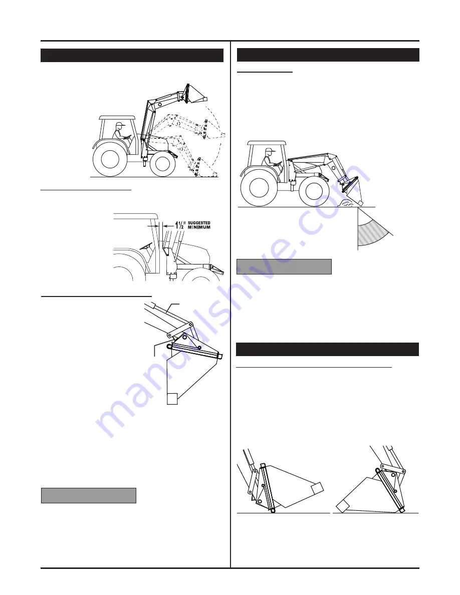
BACKGRADING - 

When back-grading with a mechanical 

self-leveling loader, be sure and keep the bucket angle 
at 40° or LESS.  If you go beyond the 40° you may dam-
age the loader’s self-leveling linkage from the excessive 
pressure being applied against them. 
Backgrade with heel of bucket only, or use optional 
BACKDRAG BLADE.  Place control lever in float position 
so bucket follows the contour of the surface.

The mechanical self-leveling loader utilizes a system of 
linkages and hinge plates that keeps the bucket in the 
position you set it during operation.  
You will not have to keep adjust-
ing the bucket when raising 
or lowering the 
loader arms.

CHECK FOR CLEARANCE -  

Protect your cab during the 

first time mounting of your self-leveling loader or add-on 
self-leveling kit.  Raise the loader slowly, as you do this, 
check for clearance.  
You should maintain 
1-1/2” or more clear-
ance between the 
rear linkage arms 
and the cab when 
the loader is fully 
raised.

Mechanical Self-Leveling

NEVER ALLOW THIS POSITION 

The self-leveling linkage will 
maintain the bucket position 
you set it in before you begin 
raising the loader.


DO NOT

 DUMP BUCKET 

FULLY AND  RAISE  THE 
LOADER. The linkage 

must


move forward to function. If 
the bucket is set in the fully 
dumped position, the linkage 
will not have room to adjust 
when the loader is raised. 

 
A built-in hydraulic relief valve on loader will relieve some 
stress if the loader accidentally gets into this position. 
It is not recommended to operate in this position as it 
will cause damage to the self-leveling if not avoided.   A 
high pitched squeal is an indication that the relief valve 
is bypassing and you should STOP and adjust bucket 
away from the Arm Stop to prevent damage.

40°

90°

DANGER 

ZONE

 LOADER 

DAMAGE. 


To prevent loader damage:

•  DO NOT  fully dump the bucket and raise loader with 

mechanical self-leveling loader.

•  STOP if loader is squealing, adjust bucket angle away 

from arm stop to avoid serious damage to loader self-
leveling linkage, loader and/or tractor.

LOADER DAMAGE.

NOTICE

INCORRECT

Bucket Cylinder

Arm 

Stop

 LOADER 

DAMAGE. 


To prevent loader damage:

•  Backgrade with “heel” of bucket only, or use optional 

BACKDRAG BLADE.

•  Place control lever in float position to reduce down 

pressure allowing bucket to follow or float along the 
contour of the ground. 

LOADER DAMAGE.

NOTICE

Mounting & Dismounting

DISMOUNTING A SELF-LEVELING LOADER:

When the lift cylinders are extended, allowing the front 
wrap to lower to the ground, the self-leveling linkage will 
reposition the bucket (trying to keep it level).  To compen-
sate for this movement, set the bucket in the load carrying 
position or fully rolled back when dismounting loader.

Once front wrap fully extends to ground, the bucket will be 
slightly tipped forward allowing moisture to run out. 

DO NOT

 curl the bucket into the fully dump position and try 

to dismount, this will cause the relief valve to bypass and 
may cause damage to the loader or tractor.

CORRECT

INCORRECT

LOAD 

CARRYING

POSITION

Summary of Contents for MAX420

Page 1: ...1 Westendorf Manufacturing Co Inc WESTENDORFMFG RR315270 MAX Loaders MAX420 440 Max Loader...

Page 2: ...ing your new equipment It should be your rst not last resort when dealing with questions Thank you for your purchase of our product If there is anything further we can do to assure complete satisfacti...

Page 3: ...omatic Quick Change System 13 Remote Coupler Dismounting 13 Remote Coupler Mounting 13 Approved Attachments 14 Section 4 Operation Safety Live With It 15 Pre Operation Checklist 15 Preparing The Tract...

Page 4: ...ose parts or equipment purchased from other manufacturers Although the Westendorf loader is designed to minimize tractor strain the manufacturer will assume no responsibility for damage to tractors or...

Page 5: ...ued or under the in uence of alcohol prescription or non prescription medication Keep equipment in proper working condition Unauthorized modi cations to the equipment may impair the function or more i...

Page 6: ...to offset the loader in front of the front tires Extreme care and slow speed must be used when raising and dumping a load Monitor the load at all times Detach Loader Safely Detach loader on a rm and l...

Page 7: ...ng the 2 Lever control Hydraulic Control Functions 1 LEVER CONTROL 2 LEVER CONTROL ASAE standard S335 4 shown in above illustrations Prevent Falling Loads ALWAYS secure the load at the source Round ba...

Page 8: ...f minimum tread settings are not available in your mounting instructions minimum rear tread settings should be selected from the following chart Minimum Tread Settings STEP 1 Put weight in the bucket...

Page 9: ...gible you can order replacements free of charge by writing to Westendorf Mfg Co Inc PO Box 29 Onawa IA 51040 0029 SAFETY DECALS To protect you and others against death and serious injury All decals sh...

Page 10: ...ements free of charge by writing to Westendorf Mfg Co Inc PO Box 29 Onawa IA 51040 0029 SAFETY DECALS To protect you and others against death and serious injury All decals shown must be on the loader...

Page 11: ...s Manual for correct procedure Loader Mounting 3 Connect hoses and electronic circuit with the Hydra Snap See section 4 for operation 5 Extend BUCKET cylinders to engage lower tower bushing A into mo...

Page 12: ...Operator s Manual for correct procedure 10 Fully dump loader bucket and lower arms to the ground as shown WARNING Crushing hazard Prevent loader from tipping by dismounting with approved bucket on rm...

Page 13: ...e hands to remove obstructions while pins are under pressure 2 Raise loader 3 to 5 feet off the ground Roll back the attachment until it is seated fully against adapter 3 PUSH and HOLD button 3 5 seco...

Page 14: ...8 Heavy Duty Fork Lift w 48 Teeth z z z z z z z z z z z z z z z z z z z z z z z z z z z z z z FLA 42 Fork Lift w 42 Teeth z FLM 42 Fork Lift w 42 Teeth z z z z z EXTENDABLE BOOM EB 34 Extendable Boom...

Page 15: ...der before mounting the loader Keep the bracket mounting instruction stored with this Operator s Manual NOTICE TRACTOR DAMAGE To prevent tractor damage Remove front tractor weights Keep front wheel bo...

Page 16: ...to roll the bucket or attachment back after dumping FLOAT The oat position allows the bucket or attach ment to follow the contour of the surface To place control lever in oat lower the bucket or atta...

Page 17: ...lose cover to protect ports from dust and debris 2 TO CONNECT Hold handle at 12 o clock position and rotate handle clockwise slowly until couplers and electronic circuit engage Close 2 relief valve Op...

Page 18: ...and toward you simultane ously to raise and rollback the bucket to breakaway the load from the pile Raise and rollback the bucket to increase your ef ciency when lling the bucket A level bucket throug...

Page 19: ...caution when operating on a slope Keep the load as low as possible This keeps the center of gravity low and provides maximum tractor stability To prevent electrocution NEVER let equipment near or cont...

Page 20: ...d place control lever in oat detent This will allow the bucket to oat and follow the surface contour To place control lever in oat lower bucket or attachment and push control lever fully forward into...

Page 21: ...t in hydraulic relief valve on loader will relieve some stress if the loader accidentally gets into this position It is not recommended to operate in this position as it will cause damage to the self...

Page 22: ...ovement Operate loader from the operator s seat only Remain at the controls until the operation cycle is fully complete Lock out valve detent when operating loader See your tractor operator s manual 3...

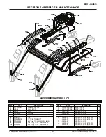
Page 23: ...23 Westendorf Manufacturing Co Inc WESTENDORFMFG RR315270 MAX Loaders SECTION 5 SERVICE MAINTENANCE...

Page 24: ...TSIDE TOWER UPRIGHT LEFT 1 RZT 12AS R INSIDE TOWER UPRIGHT RIGHT 1 RZT 12AS L INSIDE TOWER UPRIGHT LEFT 1 RZT 20AS HYDRA SNAP MOUNT 1 RZT 25AS SMART LOCK 2 RZT 27 FLIPPER 2 RZT 29 BUSHING 2 RZT 30 WAS...

Page 25: ...RZF 204AS FRAME MAX 440 1 RZF 110 BUCKET LINKAGE 2 RZF 110AS L BUCKET LINKAGE LEFT 1 RZF 110AS R BUCKET LINKAGE RIGHT 1 RZF 115AS BUCKET LINKAGE 2 RZF 151 KIT JACKET KIT RIGHT 1 RZF 152 KIT JACKET KI...

Page 26: ...1 47 GRD 60 GAUGE TUBE 1 GRD 61 ADJUSTMENT PLATE 1 GRD 175 POINTER 1 GRD 262AS BUCKET INDICATOR 1 GRD 269AS MOUNTING PLATE 1 GRD 272 TORSION SPRING 1 DE GRD DECAL 1 LM 4 NYLON BUSHING 1 5 3 57 6 5 37...

Page 27: ...16 O ring TO 3 8 FNPT SWIVEL 1 PF OS06 9 16 O ring TO 3 8 FNPT SWIVEL 3 PF STBT04 7 16 JIC O RING BRANCH TEE 2 5 3 57 6 5 37 21 47 H02080 RRDYNA MICRO HOSE 2 H02110 RRDYNA MICRO HOSE 2 H06016 6Q HYDRA...

Page 28: ...BAND 6R 6 PLASTIC BAND RED 1 5 3 57 6 5 37 21 47 B 67 CYLINDER 1 L 63 LIFT CYLINDER 1 PF POHH04 7 16 HOLLOW HEX PLUG 2 54CK SEAL KIT B 67 1 52CK SEAL KIT L 63 1 5 3 57 6 5 37 21 47 DEC 420 DECAL KIT M...

Page 29: ...40 SERIES 2 HHS0616016 3 8 X 1 BOLT 2 HTN0616 3 8 LOCK NUT 2 5 3 57 6 5 37 21 47 QC 4001COM REMOTE COUPLER 1 QC 4001AS MALE COUPLER 1 QC 3 BOTTOM LATCH PIN 1 M 19 COUPLER CYLINDER 1 XAF 55AS LINKAGE P...

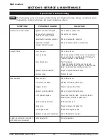
Page 30: ...f I s r e l p u o c t a c i l u a r d y h t c e n n o c s i D t i k r i a p e r l a e s l l a t s n I k a e l l a n r e t n i n a s e r e h t p m u p c i l u a r d y h e c a l p e r r o r i a p e R d...

Page 31: ...i r O e c a l p e R s e l b a c t s u j d A n e h w l o r t n o c t l i t t e k c u b f o s s o L y l e t e l p m o c d e h s u p s i r e v e l d r a w r o f n o i t i s o p t a o l f n i r e v e l l...

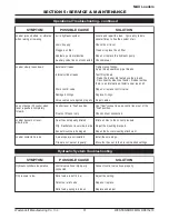
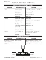
Page 32: ...e t h g i T s e s o h d n a s g n i t t i f e v i t c e f e d e c a l p e R t i k r i a p e r l a e s a l l a t s n I e v l a v e h t e c a l p e r r o r i a p e R s g n i r O e c a l p e R t o h o o...

Page 33: ...i n o i t a i r a V s e m a r f r o t c a r t n i n o i t a i r a V e d i s g n o r w n o e b y a m s t e k c a r B m e h t n e t h g i t n e h t e s o o l n o s t e k c a r b l l a t l o B s t e k c...

Page 34: ...eparation for Storage Replace damaged or missing parts including hoses pins hardware and decals Clean the loader thoroughly Dirt attracts moisture which causes rust Coat exposed cylinder rams with a t...

Page 35: ...35 Westendorf Manufacturing Co Inc WESTENDORFMFG RR315270 MAX Loaders NOTES...

Page 36: ...MAX Loaders 36 WESTENDORFMFG RR315270 Westendorf Manufacturing Co Inc SECTION 5 SERVICE MAINTENANCE...

Reviews:

Related manuals for MAX420