background image

Summary of Contents for 10.0 BEG

Page 1: ...12 5 KW 60Hz 10 0 KW 50Hz aEG 15 0 KW 60Hz 12 0 KW 50Hz BEG MARINE GASOLINE GENERATORS Sin Phase REVISION3 JANUARY 2018 member WESTERBEKf E CORPORATION MYLES STANDISH INDUSTRIAL PARK 150 JOHN HANCOCK...

Page 2: ...s Nausea Headache Weakness andSleepiness Throbbing in Temples Muscular Twitching Vomiting Inabilityto Think Coherently IF YOU ORANYONE ELSE EXPERIENCEANYOF THESE SYMPTOMS GETOUTINTO THEFRESHAIR IMMEDI...

Page 3: ...Gasoline with an ETHANOL content higher than 10 o E10 is not allowed and may void warranty r WESTERBEKE Engines Generators...

Page 4: ...Blank page...

Page 5: ...other potential sources of spilled fuel orfuel vapors Use a suitable container to catch all fuel when removing the fuelline carburetor orfuel filters 111 Do not operate with the air cleaner silencer...

Page 6: ...r into the eyes inadvertently when removing electrolyte caps TOXIC EXHAUST GASES A WARNING Carbon monoxide CO is adeadlygas 11 Ensure that the exhaust system is adequate to expel gases discharged from...

Page 7: ...t l follow ailsafety procedures GASOLINE ENGINE AND GENERATOR INSTALLATIONS Preparations to install a gasoline engine or generator should begin with a thorough examinatiqn ofthe American Boat and Yach...

Page 8: ...the vessel s waterline under the vessel s various operating conditions install a siphon break AVAILABLE FROM YOUR WESTERBEKE DEALER NOTE A siphon break requires periodic inspection and cleaning to en...

Page 9: ...Engine Adjustments 22 Spark Plugs 22 High Tension Cords 22 Drive Belt Adjustments 22 High Speed Hertz Adjustments 23 Governor Adjustments 23 Timing Belt Inspection and Replacement 24 Engine Compressi...

Page 10: ...RTS IDENTIFICATION HEAT EXCHANGER LEFT SIDE CONTROL WATER TEMPERATURE SWITCH HEAT EXCHANGER OIL DRAIN SWITCH CONTROL PANEL GENERATOR WATER INJECTED EXHAUST ELBOW PCVVALVE RIGHT SIDE Engines Generators...

Page 11: ...nd catalogs provided from sources other than WESTERBEKE are not within WESTERBEKE S CONTROL WESTERBEKE CANNOT BE RESPONSIBLE FOR THE CONTENT OF SUCH SOFTWARE MAKES NO WARRANTIES OR REPRESENTATIONS WIT...

Page 12: ...ed and serviced in the field This is up to the buyer owner operator NOTE Six important steps to ensure long generator life Proper engine andgenerator installation and alignment An efficient weU des gn...

Page 13: ...engine break in MUST be performed using conventional oil dil change intervals must be as listed in the MAINTENANCE SCHEDULE section in this manual and not to be extended if synthetic oils are used NO...

Page 14: ...and the coolant recovery tank may need to be filled to the MAX level OIL FILL Q 6 Visually examine the unit Look for loose or missing parts disconnected wires unattached hoses and check threaded conne...

Page 15: ...the STOP switch remove the 8 amp fuse or disconnect the battery A CAUTION Prolongedcranking intervals without the engine starting can result in the engine exhaust system filling with raw water This m...

Page 16: ...s reached 600 rpm s The purpose of the LED is to alert the operator to release the START switch It is also an indication that the engine generator is running REMOTE INSTRUMENTPANEL HARDWIRED An option...

Page 17: ...hourmeter reading in your log engine hours relate to the maintenance schedule Visually inspect the engine for fuel oil or water leaks Check the oil level dipstick Check the coolant level in the coolan...

Page 18: ...the engine s oil gallery Normally open in a static state this switch s sensor monitors the engine s oil pressure Should the engine s oil pressure fall to 5 l0 psi this switch will open interrupting t...

Page 19: ...d switch NOTE Overspeed switches draw a small amount ofamperage 25 milliamps at all times once the generator is connected to its starting battery This amounts to approximately 18 amp hours in a month...

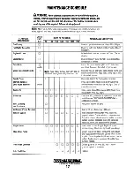
Page 20: ...lt tension Sparks Plugs 0 0 0 0 0 0 Check gap inspect for burning and corrosion Starting Batteries 0 Every 50 operating hours check electrolyte levels and House Batteries weekly and make sure connecti...

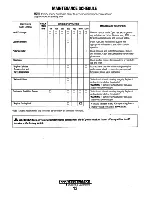
Page 21: ...motor pinion drive 0 D Check ignition timing Check condition of distributor cap and rotor 0 0 Incorrect valve clearance will result in poor engine performance check compression pressure and timing an...

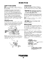
Page 22: ...eating problems A CAUTION Proper cooling system maintenance is critical a substantial number ofengine failures can be traced back to coollng system corrosion Drain the engine coolant by removing the d...

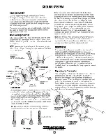
Page 23: ...the anode with another wrench This prevents the hex boss from possibly tearing off the exchanger shell If the zinc is in poor condition there are probably a lot of zinc flakes within the exchanger Rem...

Page 24: ...e valve Run the engine and check fpr leaks around the pump Also check for water discharge at the stern tube Absence of water flow indicates the pump has not primed itseif properly NOTE Never allow the...

Page 25: ...WARNING Used engine oil contains baimful contaminants Avoidprolongedskin contact Clean skin andnails thoroughly using soap and water Launder or discard clothing orrags containing used oil Discard used...

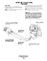
Page 26: ...ECTION HOSE MUST ATIACH TO THE IN CONNECTION AT THE REMOTE Oil FILTER To install simply remove the engine oil filter and thread on WESTERBEKE s remote oil filter kit as shown Always install this kit w...

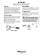
Page 27: ...and read the oil pressure gauge Oil Pressure Belween 50 and 60 psi ai18DO rp_m Note A newly started cold engine may have an oil pres sure up to 70 or 80 psi A warmed engine can have an oil pressure a...

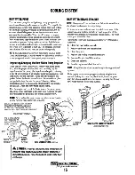
Page 28: ...ric solenoid operated choke Refer to the following pages INLET FUEL FILTER 1 Shut off the fuel supply to the generator Disconnect the fuel supply line to the inlet filter and unscrew the filter from t...

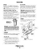
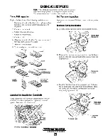
Page 29: ...be removed by releasing the hold down clamp Clean after the first 50 hours of operation every 100 hours from then on Clean the air screen in a water soluble cleaner such as GUNK Fuel Filter To ensure...

Page 30: ...00 hours from then on Clean the air screen in a water soluble cleaner such as GUNK Fuel Filter To ensure proper operation there must be a Coast Guard approved filter water seperator 10 microns or less...

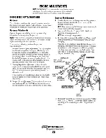
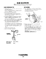
Page 31: ...ump fresh water pump drive belt loosen the two raw water pump mounting bolts 3 With the belt s loose inspect for wear cracks and frayed edges and replace if necessary 4 To loosen or tighten the govern...

Page 32: ...nt connectors are properly lubricated Use graphite lube for this purpose Disconnect the ball joint and apply graphite lube to the inside of the joint 2 Hunting Regulation Adjustment If the variation i...

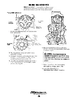
Page 33: ...OLT 5 BELT TENSlONER 1 UPPER COVER 9 ENGINE SUPPORT BRACKET 8 CAMSHAFT SPROCKET TIMING BELT ASSEMBLY 10 BELT REAR COVER 6 CRANKSHAFT PULLEY TIMING BELT NUMBERS INDICATE THE ORDER OF DISASSEMBLY 4 TENS...

Page 34: ...D 5 7 8 Sprocket Bolt Installation Camshaft Using the special tools shown in the illustration lock the camshaft sprocket in position and tighten the camshaft sprocket bolt to the specified torque LOCK...

Page 35: ...the crankshaft sprocket camshaft sprocket and tensioner pulley in that order 4 Loosen the tensioner pulley mounting bolts by 1 4 to 112 of a turn and allow the tensioner spring to apply tension to the...

Page 36: ...tional of oil causes an increase of pressure the piston ring and or cylinder wall may be worn or damaged b If additional oil does not increase compression pres sure suspect poor valve contact valve se...

Page 37: ...distributor 8 Faulty run relay K2 9 Faulty wire connection 10 No engine compression 11 Filters are clogged by contaminated fuel 12 Voltage drop at at overspeed switch 13 Faulty overspeed switch by pas...

Page 38: ...aust smoke 1 Dirty flame arrester 4 Dirty flame arrester discharge from the 2 Faulty carburetor 5 Cracked distributor cap engine 3 Idle mixture jet too rich 6 High exhaust back pressure 4 Accelerator...

Page 39: ...ator is faulty have a qualified technician check it The alternator charging circuit charges the starting battery and the service battery An isolator with a diode a solenoid or a battery selector switc...

Page 40: ...nevershut o the engine batteryswitch while the engine is running Shut o the engine batteryswitch however to avoid electrical shorts when working on the engine s electrical circuit BAnERY The minimum...

Page 41: ...PDr J l_ 4 r 4 1 1 6 RE D r _ 4 t i 1 2R ED WH T 4 S I 1 L t 1 6 W H T IY E _L _ _ r1 f _ 1 _I 6 W H _T Y E L _ t H 7 _ J CKT I 1 I L_ w q 1 1 WHTIYEL 116 VIO I JIG BLK tit WHTI i El TB2 II 101i1 0tlU...

Page 42: ...s 6 fsc s________ J KI START r o 1 _8 6 r8 5 L __ l STOP SWITCH L __ l L __ l ON SWITCH STOP SWITCH CKT I REMOTE PANEL CONNECT ONS 43912 START SWITCH CKT 2 LED 33 CHOKE SOL Oil PRESSURE SENDER fBZ l O...

Page 43: ...t v 19 AMrsTAl r 1 6 AMP RUN I 7V7B 5 l II P JlE I 7ZJ7B2 1 I L I DLVt I 70782 2 I 114 TAN I I I I TBI r 4 114 BLACK I U I Z 1 7E2 5 I I I I II PURPlE 116 LT BlUE Ill TAN 116 BLACK V LTS w 70 TB 1 oC...

Page 44: ...STOP ell ll PUR TRIPE 112 RED W PUR STRIPE v co II D a N 11 B LA CK ____ 7 J 1B1_6 H S 782 5 T4 3 12 A M P S TA R TI N G YE l W_I_R E_D_ST R IP_E WT8r4 t7 9 A MP msT A R l NG R_E_D_W_J_P_UR __ sT_R_IP...

Page 45: ...1 1 4 B LK I I LED I RED I I I I 1 ON SW WHITE RED WHITE I I I WHITE I I L 1 I I L__ I I I I I L_ _ _ _ _ _ _ _ _ _ _ _ _ _ _ _ _ _ _ _ _ _ _ _ _ _ _ _ 14 WHT RED 14 YELl RED 14 WHT 14 RED VIO PLUG I...

Page 46: ...n stroke called pinion gap 3 If the pinion gap is not within the standard range 0 5 to 2 0 mm adjust it by increasing or decreasing the number of shims on the solenoid The gap is decreased as the numb...

Page 47: ...ve the center bracket At the same time the washers for the pinion shaft end play adjustment will come off STARTER MOTOR PINION SHAFT INSPECT FOR WEAR CHIPPING 4 Return test With a battery connected to...

Page 48: ...ltAChotlegfor the vessel distribution panel This will ensure good motor starting responsefrom the generator GENERATOR FREQUENCY ADJUSTMENT Frequency is a direct result ofengine generator speed as indi...

Page 49: ...from ano load condition to a full rated generator output and from power factot LO with ngine drive speed variations up to 5Hz 1 With the alternator running at no load at normal speed and with VOLT adj...

Page 50: ...llow the steps below Configure the AC terminal block for the desired voltage frequency as shown Ensure that the case ground wire is connected to the correct terminal block neutral ground stud 3 R emov...

Page 51: ...irl ffi E _ 2 s ffi o BLACK small 0 CD ffi g5 w w J co GENERATOR VOLTAGE REGULATOR 046446 GREEN RGRAY W2 Y l r YELLOW U1 Q BLACK V e 2 120V 60Hz W2 0 V2 0 w9 AC TERMINAL BLOCK _ iJWHITL REDtAVR l 11...

Page 52: ...ENSING The voltage sensing connections are 0 and 115 when selected output voltage is between 1OOV and 140V Connect between 0 and 230 when selected output voltage is between 200V and280V EXCITER WINDIN...

Page 53: ...orted or open diodes on exciter rotor 1 Faulty voltage regulator 3 Shorted or open main stator auxiliary winding 2 Short or open to wiring to voltage regulator 1 Reset voltage potentiometer 4 Faulty v...

Page 54: ...ller s responsi bility to make sure all AC connections are correct 230 VOLT 50 HERTZ TWO WIRE CONFIGURATION z w IU 0 G N L1 GENERATOR SHORE SWITCH PN 32133 SHIP S LOAD 5 5 N NEUTRAL I 7 SHORE POWER 23...

Page 55: ...in breakerless type 14mm X1 25 pitch IGNITION SYSTEM CONT Throttle Body Electronic fuel injection with Electronic Governor 46 Spark Plug Gap General Fuel Fuel Consumption B OKw to 15 0Kw Fuel Filter...

Page 56: ...uto timing controller ignition coil built in breakerless type Spark Plug Thread Size 14mmX1 25 pitch Spark Plug Gap 030 inches 0 8 mm General Fuel Fuel Consumption 6 4Kwto 12 0Kw Fuel Filter on engine...

Page 57: ...hemicals which can reduce the life ofyour engine s internal parts 48 Fuel System Gasoline Top off your fuel tanks with unleaded gasoline of 89 octane or higher A fuel conditioner such as Sta Bil gasol...

Page 58: ...d Wipe off grime and grease and touch up any unpainted areas Protect the coupling and the output flange with an anti corrosion coating Check that the transmission vent is open For additional informati...

Page 59: ...Ounces Pounds lb x 454 Kilograms kg x 2 205 Pounds PRESSURE Pounds Per Sq In psi x 6 895 Kilopascals kPa x 145 psi Inches of Mercury Hg x 4912 psi x 2 036 Hg Inches of Mercury Hg x 3 377 Kilopascals k...

Page 60: ...0 597 605 820 14 435 590 675 915 M27 41 mm 295 400 417 565 811 1100 1154 1565 M30 46mm 402 545 568 770 1103 1495 1571 2130 1 8 590 800 660 895 910 1234 14 660 895 990 1342 M33 51 mm 546 740 774 1050 1...

Page 61: ...R BRAND FOR AN OIL CHANGE 5 QTS ANDA GALLON OF PREMIXED COOLANT SPARE PARTS KITS WESTERBEKE also offers two Spare Parts Kits each packaged in a rugged rust free toolbox KIT A includes the basic spares...

Page 62: ......

Page 63: ......

Page 64: ...Engines Generators 1167 12 2011...

Reviews: