background image

Summary of Contents for 13.5 KW EDE

Page 1: ...tz at 50 Hertz SINGLE AND THREE PHASE FIRST EDITION JULY 2008 WESTERBEKE WESTERBEKE CORPORATION MYLES STANDISH INDUSTRIAL PARK 150 JOHN HANCOCK ROAD TAUNTON MA 02780 7319 TEL 1 508 823 7677 FAX 1 508...

Page 2: ...alattention Shutdown the unit and do not restart until it has been inspected andrepaired WARNING Generatoffi Pnx1UC6 CARBON MONOXIDE Regular Maintenanca Required AWARNING DECAL isprovidedby WESTERBEKE...

Page 3: ...iring Diagrams 75 Generator Assembly 76 BE Troubleshooting 78 Metric Charts 79 Hardware Torques 81 SERIAL NUMBER LOCATION The engine s model number and serial number are located on a nameplate mounted...

Page 4: ...e until piston rings and valve seats have been broken in Thereafter it decreases gradually with the progress of wear of these parts When decrease of compression reaches the repair limit the engine mus...

Page 5: ...Injection too early 6 Adjust injection timing MAIN ENGINE TROUBLES 1 Low compression a Incorrect valve clearance a Adjust valve clearance b Inadequate contact of valve seat b Lap valve c Valve stern s...

Page 6: ...ston ring 3 Replace ring 4 Worn piston or cylinder 4 Replace piston and rabore cylinder OIL LEVEL FALLING 1 Defective stem seal 1 Replace stem seal 2 Worn valve and valve guide 4 Replace avalve and va...

Page 7: ...High oil pressure 1 Dirty oil or wrong SAE type oif in the engine 2 Relief valve is stuck Black exhaust smoke 1 Dirty flame arrester discharge from the 2 Lube oil is diluted engine 3 Valves are worn o...

Page 8: ...the oil can be the result of a fault in the exhaust system attached to the engine and or a siphoning of raw water through the raw water cooling circuit into the exhaust filling the engine This problem...

Page 9: ...portant Too thin a bead could cause leaks and too thick a bead could be squeezed out of location causing blocking or narrowing of the fluid feed lines To eliminate the possibility of leaks from ajoint...

Page 10: ...al for HEAT EXCHANGER service ENGINE TUNING OPERATION After re assembly the engine must be tuned This will ensure that the engine operates at its maximum efficiency Fill the engine cooling system with...

Page 11: ...Detach the injection pipes When Reassembling Blowout dust inside the pipes TIGHTENING TORQUE INJECTION PIPE RETAINING NUT__24 5 34 3 N m 2 5 3 5 Kgf m 18 1 25 3 ft Ibs NOZZL HOLDER ASSEMBLY AND GLOW...

Page 12: ...cylinder head gasket with a new one 2 Tighten the cylinder head screws after applying sufficient oil 3 Tighten the cylinder head screws in a diagonal sequence starting from the center in the order of...

Page 13: ...and the valve guide INJECTION PUMP 1 Remove the stop solenoid and the hi idling body 2 Remove the engine stop lever and stop solenoid guide 3 Remove the fuel injection pump assembly NOTE Before remov...

Page 14: ...late 2 Put the specific tool from the injection pump side to catch the large governor spring Keep this spring slightly extended and place the speed control plate in its specified position 3 Using the...

Page 15: ...L__ TOOL 3 Remove the drive pulley with gear puller 4 Remove the feather key When Reassembling Apply grease to the splines of the coupling TIGHTENING TORQUE FAN DRIVE PULLEY MOUNTING NUT 137 3 156 9 N...

Page 16: ...ing 1 Insert the crankshaft collar after installing the gear case to the cylinder body CRANKSHAFT OIL SLINGER CRANKSHAFT COLLAR OIL PUMP DRIVE GEAR I IDLER GEAR 1 Remove the external snap ring 2 Detac...

Page 17: ...d 4th cylinder pistons at the top dead center in compression then align all marks on each gear to assemble the timing gears set the idle gear last TIGHTENING TORQUE CAMSHAFT SET BOLT 23 5 27 5 N m 2 4...

Page 18: ...on upward by lightly tapping it from the bottom of the crankcase with the handle of a hammer S Draw out the other piston in the same method as above When Reassembling 1 Before inserting the piston int...

Page 19: ...onto the piston place the expander joint on the opposite side ofthe oil ring gap 3 Apply engine oil to the piston pin 4 When installing the piston pin immerse the piston in 80 C 176 F oil for 10 15 mi...

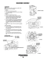
Page 20: ...er mounting screws Remove the inside screws first and then the outside screws 2 Screw the two removed screws into the screw hole of the bearing case cover to remove it NOTE The length ofthe inside scr...

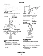
Page 21: ...til the crank pin of the first cylinder comes to the center of the third cylinder 4 Repeat the above steps to draw the crankshaft completely out When Reassembling 1 Install the crankshaft sub assembly...

Page 22: ...meters of the main bearing cases may vary so install them in the order of the markings A B for 3 cylinders and A B C for 4 cylinders from the gear case side 4 Match the alignment numbers and mark on t...

Page 23: ...water pump assembly from the gear case cover 4 Remove the water pump flange 5 Press out the water pump shaft with the impeller on it 6 Remove the impeller from the water pump shaft 7 Remove the mecha...

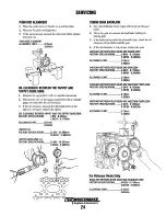
Page 24: ...on 2 Measure the valve stem O D with an outside micrometer 3 Measure the valve guide LD with a small hole gauge and calculate the clearance 4 If the clearance exceeds the allowable limit replace the v...

Page 25: ...ry After correcting the valve seat be sure to check the valve recessing Correcting the Valve 1 Correct the valve with a valve refacer Correcting the Valve Seat 1 Slightly correct the seat surface with...

Page 26: ...417 1 6614in ALLOWABLE LlMIT____ 41 2mm 1 6220in TILT ALLOWABLE LlMIT____1 0mm 0 039in VALVE SPRING SETTING LOAD 1 Place the valve spring on a tester and compress it to the same length it is actually...

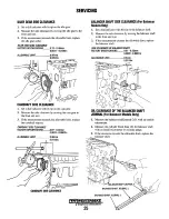
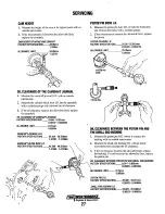
Page 27: ...ASH 1 Set a dial indicator lever type with its tip on the gear tooth 2 Move the gear to measure the backlash holding its mating gear 3 If the backlash exceeds the allowable limit cheek the oil clearan...

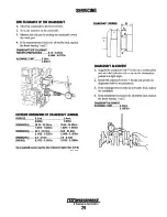
Page 28: ...28 0 00871n ALLOWABLE LlMIT____ O 30mm 0 01181n BALANCER SHAFT SIDE CLEARANCE For Balancer Models Only 1 Set a dial indicator with the tip on the balancer shaft 2 Measure the side clearance by moving...

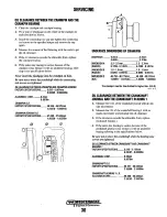
Page 29: ...r gear bushing 1 0 with an inside micrometer and calculate the oil clearance 3 If the oil clearance exceeds the allowable limit replace the bushing 4 If it still exceeds the allowable limit replace th...

Page 30: ...PISTON PIN BORE 1 0 1 Measure the piston pin bore I D in both the horizontal and vertical directions with a cylinder gauge 2 If the measurement exceeds the allowable limit replace the piston PISTON PI...

Page 31: ...om the ring grooves 2 Measure the clearance between the ring and the groove with a feeler gauge or depth gauge 3 If the clearance exceeds the allowable limit replace the ring 4 If the clearance still...

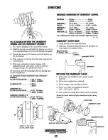
Page 32: ...1 0413In DIMENSION B_ 54 5 54 7mm 54 6 54 Smm 2 1456 2 1535in 2 1496 2 15741n DIMENSION C_2 B 3 2mm 2 B 3 2mm RADIUS 0 1102 0 12601n 0 1102 0 1260in The crankshaft journal must be fine finished to hig...

Page 33: ...2201n UNDERSIZE DIMENSIONS OF CRANKPIN UNDERSIZE__ 0 2mm 0 4mm DIMENSION A RADIUS DIMENSION B RADIUS DIMENSION C DIA 0 008in 0 0161n 3 3 3 7mm 3 3 3 7mm 0 1299 0 14571n __0 1299 0 14571n 1 0 1 5mm 1 0...

Page 34: ...kshaft journal must be fine finished to higher than 0 8 S V r V REPLACING THE CRANKSHAFT BEARING 1 Whell Removillg 1 Press out the used crankshaft bearing 1using a crankshaft bearing 1replacing tool W...

Page 35: ...0 D25mm 2 36142 2 363180in REFER TO THE DATA IN THE UPPER RIGHT STOPPER UNDERSIZE DIMENSIONS OF CRANKSHAFT JOURNAL UNDERSIZE___D 2mm______0 4mm DIMENSION A RADIUS 0 008in 0 0161n 2 8 3 2mm 2 8 3 2mm 0...

Page 36: ...3 43590in MAXIMUM WEAR ALLOWABLE LlMIT____ O 15mm 0 0059In FINISHING HORN TO 2 2 3 0 UM Rmax 00g l7 0 00118 in Rma _V r VV 2 Replace the piston and piston rings with oversize O 2Smm ones When the ove...

Page 37: ...I I I I II I I L __ I I I I 1 I I I II p rI I II x x 2 I m I 0 u I h I I t____ l ______ J Engines Generators 34...

Page 38: ...fiiN I I ZlrJ 1DI r I 7l I nltll t _____ 1 Til I I _ _ _ J I I I 1 _ Ii I L I I 1 000 10 1 0 1 I 001 000 I 1 11 r I I II I I n 1 _ 1 I I I I I J...

Page 39: ...he alternator Drive belts that are too tight will pull the alternator out of alignment and or cause the alternator to wear out prematurely Excessive drive belt tension can also cause rapid wear of the...

Page 40: ...move the hand lever at intervals ofone stroke per second while read ing tile injection starting pressure A CAUTION The sprayinjected from the norzle is Dfsuch velocity that it maypenetrate deeply int...

Page 41: ...counterclockwise to see if the piston is at the compression top dead center or the overlap position Now referring to the table below readjust the valve clearance The piston is at the top dead center w...

Page 42: ...tor faults When re installing the glow plugs use anti seize compound NOTE Do not guess the conditions ofother cylinders from a result oftesting one cylinder Be sure to measure the compression pressure...

Page 43: ...MPU out of the opening one tum and then lock it in this position with the jam nut This will position the end of the MPU approximately 0 030 inches away from the flats of the ring gear teeth To ensure...

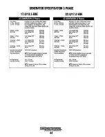
Page 44: ...ve Oil Filter Sump Capacity includes oil filter Full flow paper element spin on type 6 3 U S qts 6 0 liters LUBRICATION SYSTEM Operating Oil Pressure 28 57 psi 2 0 4 0 kg cm2 engine hot Oil Grade API...

Page 45: ...3Phase High Voltage WYE 400 Volts 50 Hertz DELTA 230 Volts 50 Hertz DELTA 230 Volts Amperage 3 phase Low Voltage WYE 51 Amps Amperage 3 phase Low Voltage WYE 66 Amps 60 Hertz High Voltage WYE 25 Amps...

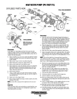
Page 46: ...other side of the circlip Install the next circlip in the recess at the shafts driven end against the shaft bearing 2 Warm the pump body on a hot plate to expand the body Then drop the shaftlbearing...

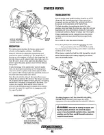
Page 47: ...FOLD GROUND WIRES REFER TO THE WIRING DIAGRAM IN THIS MANUAL FOR WIRING CONNECTIONS TROUBLESHOOTING Prior to testing make certain the ships batteries are at full charge and that the starting system wi...

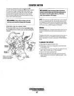
Page 48: ...ther crewmembers of the danger NOTE Starter motors are either inertia type orpre engaged In the pre engaged model the solenoid also moves an arm that engages the starter motor to the flywheel ofthe en...

Page 49: ...as been removed from terminal C 2 Connect another jumper from the battery post to the starter motor s housing momentarily If the motor fails to run the motor is the problem Magnetic Switch Test 1 Conn...

Page 50: ...exceeded Also check the commutator outside surface for dirtiness and roughness Ifrough polish the commutator with fine crocus cloth 3 Cheek the commutator mica under cut and correct with a hacksaw bla...

Page 51: ...clutch assembly 2 Check that the pinion gear turns freely and smoothly in the overrunning direction and does not slip in the cranking direction If the pinion slips or fails to rotate in both direction...

Page 52: ...EARS APPLY GREASE ROLLER RETAINER ROLLERS I GEARS APPLYGREASE t l t DISASSEMBLING THE MAGNETIC SWITCH 1 Remove the drive end frame mounting screws 2 Disassemble carefully the over running clutch ball...

Page 53: ...ntain a proper system voltage The regulator design utilizes all silicon semi conductors and thick film assembly techniques After the voltage has been adjusted to the proper regulating valve the entire...

Page 54: ...the reading should be 12 to 13 volts MEASURING BATTERY VOLTAGE IGNITION ON ENGINE OFF TESTING THE OUTPUT CIRCUIT 1 Connect the positive probe to the output terminal Band connect the negative probe to...

Page 55: ...battery charging circuit Troubleshoot the service battery charging circuit by checking the wiring and connections the solenoid isolator battery switch and the battery itself When the problem has been...

Page 56: ...olding the IC regulator and remove the IC regulator 5 Remove the 4 screws holding the rectifier and the stator lead wires remove the rectifier 6 Unscrew the 2 nuts and 2 screws that hold the drive end...

Page 57: ...appearance if it does not rotate smoothly replace the bearing 2 Measure the resistance across each lead of the stator coil with an ohmmeter If the measurement is not within factory specifications rep...

Page 58: ...ty across each rectifier diode with an analog olunmeter Conduct the test in the Rxl setting The rectifier is nonnal if the diode conducts in one direction and not in the other NOTE Do not use a 500VMe...

Page 59: ...STATOR DRIVE END ALTERNATOR SERVICE EXPLODED PARTS VIEW Ie REGULATOR Engines Generators 58...

Page 60: ...52 rad 30 B 10 mm 0 39 in C Chamter 0 3 mm 0 01 in D 182 mm 7 16 in E 140 mm 5 51in F 35 mm dia 1 38 in dia G 60 mm dia 2 36 in dia H 37 mm 1 46 in I 21 9471021 960 mmdia 0 8641 to 0 8646 in dia J 24...

Page 61: ...mm 1 06 in 0 35 mm dia 1 38 in dia I E 27 901027 95 mm di 1 098 to 1 100 in dio F 25 00 to 25 01 mm dia 0 984 to 0 9851n dia 2 For idle gear bushing A 175 mm 6 89 In B 40 mm 1 571n C 38 mm 1 49 in I...

Page 62: ...arance When Cold 0 18 to 0 22 mm 0 0071 to 0 0087 in Valve Seat Width Intake 2 12 mm 0 0835 in Width Exhaust 2 12 mm 0 0835 in Valve Seat Angle Intake 1 047 rad 60 0 Angle Exhaust 0 785 rad I 45 0 Val...

Page 63: ...0 55118 to 0 55189 in Push Rod Alignment 0 25 mm 0 0098 in Tappet to Tappet Gl lide Clearance 0 020 to 0 062 mm 0 07 mm 0 00079 to 0 00244 in 0 0028 in Tappet 0 0 23 959 to 23 980 mm 0 94327 to 0 9441...

Page 64: ...ncer Shaft Side Clearance 0 07 to 0 22 mm 0 3mm Balancer Model Only 0 0028 to 0 0087 in 0 0118 in Balancer Shaft Journal 1 to Balancer Shaft Clearance 0 030 to 0 111 mm 0 2mm Bearing 1 Balancer Model...

Page 65: ...ushing Clearance 0 014 to 0 038 mm 0 15 mm 0 00055 to 0 00150 in 0 0059 in IPiston Pin 0 0 25 002 to 25 011 mm 0 98433 to 0 98468 in _ __ Small End Bushing 25 025 to 25 040 mm 1 0 0 98523 to 0 98582 i...

Page 66: ...ltage More than 13 5 V Stator Less than 1 0 0 Resistance Rotor 2 90 Resistance Slip Ring 14 4 mm 14 0 mm i 0 0 0 567 in 0 551 in IBrush 10 5 mm 8 4mm Length 0 413 in 0 331 in Glow Plug Resistance Appr...

Page 67: ...to 3 43590 in 0 0059 in LUBRICATING SYSTEM Item Factory Specification Allowable Limit Engine Oil Pressure IAt Idle Speed 98 kPa or more 49 kPa 1 0 kgf cm2 or more 0 5 kgf cm2 14 psi or more 7 psi IEog...

Page 68: ...lder assembly M20 x 1 5 49 0 to 68 6 5 0 to 7 0 36 2 to 50 6 Oil pressure switch R 1 8 14 7to 19 6 1 5 to 2 0 10 8 to 14 5 Injection pipe retaining nut M12x1 5 24 5 to 34 3 2 5 to 3 5 18 1 to 25 3 Ove...

Page 69: ...nninal block be corifigured to provide one 120 voltAC hot legfor the vessel s distribution panel This will ensure good motor starting responsefrom the generator GENERATOR FREQUENCY ADJUSTMENT Frequenc...

Page 70: ...ng separate TillS is the case of a generator equipped with auxiliary winding for regulator supply Supply is always connected to terminals 3 and 5 of the regulator o 4A 4 3A 31 2 EXCITER FIELD 1 In bot...

Page 71: ...um counterclockwise and wait about twenty seconds During this period of time the voltage value decreases In this condition and while turning the potentiometer clockwise fix the generator voltage value...

Page 72: ...and Cto A as shown on the drawing B c EXCITER ROTOR WINDINGS VIEW OF ROTOR FROM THE BEARING END 12 a CLOCKPosmON Disconnect these three wires from the diode bridge plates taking care not to drop any...

Page 73: ...volts 10 12 2 4 10 5 7 NU L2 SO Hz L L 230 volts SO Hz L N 115 volts 60 Hz L L 271 volts 60 Hz L N 138 volts Refer to Note I L 0 o lote ttl Singlephase amperage load The phase CUl1Ymt must nQt exceed...

Page 74: ...AC output voltage fault shut down eitherfrom low or high AC voltage or incorrectAC voltage displayed on the LCD display 3 There are three line connections When an L3 is not present on the AC terminal...

Page 75: ...I PH 3 CHANGING BACKEHD BETWEEN I PHASE AND J PHASL ill 0 4 1 6 9 0 10 8t II 0 0 E OOUBl E DELTA 3 WlRE SPUT SINGLE PHASE 120 240V 60 H IIO 220V 50 HI seRIES DELTA 240V 50 Hz 220V 150 Hz PARALLEL OELT...

Page 76: ...VOLTAGE REGULATOR 120 240V 60 HZ L1 L2 f 1 AC CiRCUIT ll f I BREAKER r I L1 L2 N L1 CONDENSER I I I I I I I I I I SUP ESSO 1 f 100 Ko I I AUXILIARY 6 AC TERMINAL BLOCK BLACK GREEN BLUE SINGLE PHASE IN...

Page 77: ...ort 3 Place a large washer of at least 80rnm in diameter with a center hole of 15mm onto the threaded rod followed by a 12mm x 1 75 nut Center the rear bearing in the bearing boss of the support plate...

Page 78: ...ark the connection points the generator leds connect to Make an illustration ifneeded whether the generator is to be reinstalled or a replacement is to be installed This is to ensure proper reconnecti...

Page 79: ...D 15 20 VOLTS AC auxiliary circuit feed to AVR stator auxiliary winding 2 Faulty voltage regulator LOW AC VOLTAGE OUTPUT AT 1 Reset voltage potentiometer 4 Short in rotating field winding NO LOAD 60 1...

Page 80: ...125 17 85937 7 32 0 21875 5 55625 23 32 0 71875 18 25625 15 64 0 234375 5 95312 47 64 0 734375 18 65312 1f4 0 250 6 35000 3 4 0 750 19 05000 17 64 0 265625 6 74687 49 64 0 765625 19 44687 9 32 0 28125...

Page 81: ...x 454 Kilograms kg x2 205 Pounds PRESSURE Pounds Per Sq In psi x 6 895 Kilopascals kPa x 145 psi Inch es of Mercury Hg x 4912 psi x 2 036 Hg Inches of Mercury Hg x 3 377 Kllopascals kPa x 2961 Hg Inch...

Page 82: ...1100 1154 1565 M30 46mm 402 545 568 770 1103 1495 1571 2130 1 B 590 800 660 895 910 1234 14 660 895 990 1342 M33 51 mm 546 740 774 1050 1500 2035 2139 2900 M36 55mm 700 950 992 1345 1925 2610 2744 37...

Page 83: ...1 6 6 56168 2 1 82880 7 6 40080 2 2 18723 7 7 65529 3 2 74320 8 7 31520 3 3 28084 8 8 74891 4 3 65760 9 8 22960 4 4 37445 9 9 84252 4 57200 10 9 14400 5 5 46807 10 10 93614 MOVE DECIMAL POINT FOR HIGH...

Page 84: ...nor Springs Control Panel 11 Testing the Diodes 71 Idler Gear 13 Twelve Lead Winding Injection Pipes 8 Terminal Board Connections 72 Injection Pump 10 Hardware Torques 81 Main Bearing Case Assembly 19...

Page 85: ...Bore J D 27 Piston Ring Clearance 28 Piston Ring Gap 28 Push Rod Alignment 24 Replacing Crankshaft Bearing 1 31 Replacing Crankshaft Sleeve 32 Replacing Small End Bushing 28 Replacing Valve Guide 21...

Page 86: ......

Page 87: ...Engines Generators 1128 DWIWM IO 08...

Reviews: