background image

Summary of Contents for 16.0 BEDA

Page 1: ...z 20 0 BED 50 Hz 32 0 BEDA 60 Hz 25 0 BEDA 50 Hz Single and Three Phase PUBLICATION N0 039685 REVISIONS AUGUST 2017 WcSTERBEKECORPORATiON 1SOJ0HNHANCOCKROAD MYLES STAND S f INDUSTRIAL PARK TAUNTON MA 02780 WEBSITE WWW WESTERBEKE COM A 1f A Member NationalMarine Manufacturers Association ...

Page 2: ... gas Carbon Monoxide ispoif Jnous and can cause unconsciousness and death Symptoms ofCarbon Monoxide exposure can include Dizziness Nausea Headache Weakness andSleepiness Throbbing in Temples Muscular Twitching Vomiting Inability to Think Coherently IF YOU ORANYONE ELSE EXPERIENCEANYOF THESE SYMPTOMS GET OUTINTO THE FRESHAIR IMMEDIATELY Ifsymptoms persist seekmedicalattention Shut down the unit_an...

Page 3: ... potential sources of spilled fuel or fuel vapors Use a suitable container to catch all fuel when removing the fuel line carburetor or fuel filters m Do not operate with the air cleaner silencer removed Backfire can cause severe injury or death II Do not smoke or pennit flames or sparks to occur near the fuel system Keep the compartment and the engine generator clean and free ofdebris to minimize ...

Page 4: ...or into the eyes inadvertently when removing electrolyte caps TOXIC EXHAUST GASES A WARNING Carbon monoxide CO Is a deadlygas IB Ensure that the exhaust system is adequate to expel gases discharged from the engine Check the exhaust system regularly for leaks and make sure the exhaust manifold water injected elbow is securely attached a Be sure the unit and its surroundings are well ventilated Run ...

Page 5: ...STALII ATDONS Preparations to install an engine should begin with a thor ough examination of the American Boat andYacht Council s ABYC stanclar ds These standards are a combination of sources including the USCG and the NFPA Sections oftheABYC standards ofparticular interest are H 32 Ventilation for boats using diesel fuel H 33 Diesel Fuel Systems P 1 Installatiion ofExhaust Systems for Propulsion ...

Page 6: ...o the vessel s waterline under the vessel s various operating conditions install a siphon break NOTE A siphon break requires periodic inspection and cleaning to ensure proper operation Failure to properly maintain a siphon break can result in catastrophic engine damage Consult the siphon break manufacturerfor proper maintenance EXHAUST SYSTEM AVAILABLE FROM YOUR WESTERBEKE DEALER sJPHON MEAKWlTHST...

Page 7: ...erature Switch 8 Low Oil Pressure Switch 8 Engine Circuit Breaker 8 Generator Break In Procedure 9 Description 9 After Start up 9 Check List 9 Generator Adjustments 9 The Daily Routine 10 Check List 10 Start the Generator 10 Maintenance Schedule ll Engine Cooling Circuit 13 Description 13 Fresh Water Circuit 14 Coolant Recovery Tank 14 Engine Adjustments 28 Valve Clearance Adjustment 28 Drive Belt...

Page 8: ...y three numbers The character indicates the decade A 1960s B 1970s C 1980s D 1990s the first number represents the year in the decade and the second and third numbers the month of manufacture PRODUCT SOFTWARE Product software tech data parts lists manuals brochures and catalogs provided from sources other than WESTERBEKE are not within WESTERBEKE s control WESTERBEKE CANNOTBE RESPONSIBLE FOR THE C...

Page 9: ...asoline engine The most important factors are proper ventilation and proper maintenance of the fuel lubricating and cooling systems Replacement of fuel and lubricating filter elements at the time periods specified is a must and frequent checking for contamination that is water sediment etc in the fuel system is also essential Another important factor is the use of the same brand of high detergent ...

Page 10: ...injection pump and stopping the engine WATER TEMPERATURE GAUGE ENGINE COOLANT TEMPERATURE SHOULD INDICATE 1W T0 1 95 F 80 TO 91 C NOTE When the engine is shiP down the water temperature gauge and the oilpressure gauge will continue to register the last temperature and oilpressure readings displayed They will return to zero once electricalpower is restored 4 EMERGENCY STOP The EMERGENCY stop switch...

Page 11: ...il SAE OIL VISCOSITY For all temperature ranges SAE lSW 40 or SAE lOW 40 ENGINE COOLANT WESTERBEKE recommends a mixture of 50 antifreeze and 50 distilled water Distilled water is free from the chemicals that can corrode internal engine surfaces The antifreeze performs double duty It allows the engine to run at proper temperatures by transferring heat away from the engine to the coolant and lubrica...

Page 12: ...stem requires and that the generator neutral is properly connected to the load neutral In single phase and some 3 phase systems an incomplete or open neutral can sup ply the wrong line to neutral voltage on unbalanced loads 0 Make sure the mounting installation is secure 0 Make sure that the generator is properly grounded MANIFOLD PRESSURE CAP ENGINE OIL FILL A CAUTION When starting the generator ...

Page 13: ...TION Prolonged cranking Intervals without the engine starting can result In the engine exhaust system filling with raw water This may happen because the pump Is pumping raw water through the raw water cool Ing system during cranking This raw water can enter the engine s cylinders by way of the exhaust manifold once the exhaustsystem fills Prevent this from happening by closing the raw water supply...

Page 14: ...e exhaust elbow Normally closed this switch will open and interrupt _ the DC voltage to the fuel solenoid on the injection pump shutting OFF the engine should the switch s sensor indicate an excessive exhaust temperature an inadequate supply of raw water causes high exhaust temperatures This switch opens at 260 270 F 127 132 C This switch resets at approximately 225 F 107 C HIGH EXHAUST TEMPERATUR...

Page 15: ...n the load can be increased to the full load rated output then periodi cally vary the load Avoid overload at all times An overload is signaled by smoky exhaust with reduced output voltage and frequency Monitor the current being drawn from the generator and keep it within the generator s rating Since the generator operates at 1800 rpm to produce 60 hertz or at 1500 rpm to produce 50 Hertz control o...

Page 16: ...ages Allow the engine to warm up for 5 to 10 minutes to reach an operating temperature of 140 to 150 F 60 66 C before applying AC loads Apply loads systematically allowing the generator to adjust to each load before applying the next Check the gauges for proper oil pressure operating tempera ture and DC voltage NOTE Some unstable running may occur in a cold engine This condition should lessen as n...

Page 17: ...bolts nuts tight remain cool Check for loose belt tension Fuel Filter D D D 0 D D Initial change at 50 hrs then change every 250 hrs Starting BaHeries D Every 50 operating hours check electrolyte levels and House BaHeries weekly and make sure connections are very tight Clean off excessive corrosion Engine Oil and filter D D D D D D D Initial engine oil filter change at 50 hrs then change both ever...

Page 18: ...ten electrical connections Feed Pump Strainer 0 0 0 0 0 Clean every 250 operating hours if applicable Fuel Injectors 0 Check and adjust injection opening pressure and spray condition see ENGINEADJUSTMENTS Starter Motor 0 0 Check solenoid and motor for corrosion Remove and lubricate Clean and lubricate the starter motor pinion drive Preheat Circuit 0 0 Check operation of preheat solenoid Remove and...

Page 19: ...engine The coolant then passes through the thermostat into the manifold to the heat exchanger where it is cooled and returned to the engine block via the suction side of the circulating pump COOLANT RECOVERY TANK TYPICAL ENGINE COOLING CIRCUIT When the engine is started cold external coolant flow is pre vented by the closed thermostat although some coolant flow is bypassed around the thermostat to...

Page 20: ...cessible and can be checked cleaned or replaced easily Carry a spare thermostat and gasket Replacing the Thermostat Remove the cap screws and disassemble the thermostat hous ing as shown When installing the new thermostat and gasket apply a thin coat of sealant on both sides of the gasket before pressing it into place Do not over tighten the cap screws Run the engine and check for normal temperatu...

Page 21: ...ereby reducing the effects of elec trolysis on other components of the system The con dition of the zinc anode should be checked monthly and the anode cleaned or replaced as required Spare anodes should be carried on board NOTE Electrolysis action is the result ofeaciJ particular installation and vessel location not that ofthe generator If the zinc pencil needs replacement hold the hex boss into w...

Page 22: ...he fuel connectioil to and out of the pump and make sure that no leakage is present and that the fittings are tight and ure The DC ground connection at one ofthe pump s mounting bolts should be clean and well secured by the mounting bolt to ensure proper pump operation A WARNING Fuel leakage at the fuelpump or Its connections isa fire hazardandshouldbe corrected Makesure proper ventilation exists ...

Page 23: ... clockwise carefully until the o ring contacts the sealing surface of the housing bracket Turn 2 3 further with the filter wrench 5 Tum on the fuel and start the engine The normal preheat function should quickly prime the system d the engine should start If the engine should fail to start immediately follow the Priming instructions in this section PRESSURE GAUGE LOCATION BLEED FUEL FILTER 120 AND ...

Page 24: ...el free of air is discharging from the line stop pumping Reconnect the return line and work the pump a few more strokes Then push the cylinder in and secure it Start the engine and check correct any leaks Should unstable running occur open the nut that secures the high pressure line to the injector to expel air in the line Loosen 1 2 to a full turn place a cloth over the line and wrench to catch t...

Page 25: ...ket remains sealed against the engine block gently remove it When installing the new oil filter element wipe the filter gasket s sealing surface on the engine block free of oil and apply a thin coat of clean engine oil to the rubber gasket on the new oil filter Screw the filter onto the threaded oil filter nipple and then tighten the filter firmly by hand OIL FILTER 25 KW 32 KW _ NOTE DO NOT OVER ...

Page 26: ...EN BY HAND AN ADDITIONAL 3 4 TURN AfTER THE O RING CON TACTS THE BASE To install simply remove the engine oil filter and thread on WESTERBEKE s remote oil filter kit as shown Always install this kit with the oil filter facing down as illustrated Contact your WESTERBEKE dealer for more information NOTE Westerbeke is not responsible for engine failure due to incorrect installation ofthe Remote Oil F...

Page 27: ...ug is a small heater installed in each pre combus tion chamber They run off the engine starting battery and become red hot when activated The glow plugs are wired through the preheat solenoid When PREHEAT is pressed at the control panel this solenoid should click on and the glow plug should begin to get hot Glow plugs can be checked by unscrewing and holding them against a good ground engine block...

Page 28: ...at everyone is clear ofmoving parts Keep away from sheaves andbelts during testprocedures NOTE Multimeters and DC Circuits DC andAC circuits are often mixed together in marine appli cations Always disconnect shore power cords isolate DC andAC converters and shutdown generators before perform ing DC testing NoAC tests should be r nade without proper knowledge ofAC circuits 1 Start the Engine 2 Afte...

Page 29: ...ed at a reli able service shop NOTE Bejore removing the alternator for repair use your voltmeter to ensure that 12 vofts DC excitation is present at the EXC terminal ifthe previous test showed only bat tery voltage at the B output terminaL If12 volts is not present at the EXC terminal trace the wiring look for breaks and poor connections Alternator is Working 4 Check the voltage of the service bat...

Page 30: ... ONil 1 l m 181 1 rl LW TBH t m l i j ll JllU J J iii D Will l luR WAHR itatiATURE D Jh i f iJmJ T II UliRU 114 RED 114 BtK fS D 0 1101 1 J rn 0 amBW1m IU aro fJ t9lKt R 4 U JQr iAUX 11511Iw1WU Ill RE fl4 TAN d J S H 1f411RN ill t14 YIO I US R DIWHT Kl IU I D SI KOU tk r U4Vt0 U111t t 1 IC2 l i h c Ill Rll ttDrn Ill ORG Ill WKl HOUR METER Engines Generators 23A OIL PRESSURE SWITCH HRNATOR j Q lm 4...

Page 31: ...roubleshooting this board To by pass for test purposes ONLY Move connection 4 onto 5 BA ToP lswl TCH I PREHEAT START SWITCH EXH TEMP SWITCH IN4002 GlOWPLUGS 1 or sw_I_T_c 86 L 1 181 1 181 3 181 4 T82 2 T8H START SWITCH TB2 1 1Bc 8 TBc 4 IND LIGHT TYPICAl REMOll SHRTiSTOP PAN l CONECTIONS NOH 0 R J UlT CON CTOR PINS Engines Generators 238 AUX O P SWITCH OIL PftUS S ND R WAT R TEMP S HDER 1BI IO Oil...

Page 32: ...UST EMP SW 020 l CONNECTING A 1 0 l i t f t REMOTE PANEL Lj j __ IHH t NOTE 1 An on offswitch should be installed in this circuit to disconnect the starter from the battery in an emergency and when leaving the boat Twelve volt diesel engine starters typically draw 200 to300 amps when cranking A switch with a continuous rating of175 amps at 12 VDC will normally serve his function but a switch must ...

Page 33: ...R _ DI WH _T_ _ _ i TB2 I _ WH _T__ TB2 2 r 1c LW c RD_ f TB I 5 1 RD tr Hl W HT LIR D _J TB I 3 i REMOVE JUMPER RDIVIOTBI 2 TB B I i WHT R f rl TBI IO 14 TEL WATER TEMP 24A N tl4 RED 116 REO lllll REMOVE THIS JUMPER WHEN INSTALLING ONE REMOTE START STOP PANEL IF INSTALLING TWO PANELS REMOVE BOTH JUMPERS INSTRUMENT PMill PR IEAT SWITCH START SWITCH 5TOI SWITCH ALTERNATOR 51A FUSE 8A NOTE 1 An on o...

Page 34: ...EMOTE PANELCSI I fl RED 114 lEO 114 PUR rz i i r au au I ILK tu a 114 lED VR 0 Ttl IU It 0 lf f PUI f f Bll r 110 RUIWKT 1 c IBLK WHT r UC WNT SSr J ESJ r unic R NT I I C G fAI ll I I 1411111 01 10 ll o 1 TtL II I OIWJIT i I I PN H AT IIIITCH IJ CL WAT1 ft ill I I u u ruwtnl s r k P 248 ALTERNATOR StA l l J r NOTE 1 An on offswitch led in this nect the battery in ndwhen should be instal circuit to...

Page 35: ...ICAL SYSTEM WIRING SCHEMATIC 039422 12VDC f BATTERY SWITCH L START SOL STARTER r l t 1 M1 PREHEAT l J SOL GLOWPLUGS r t 4 1 120A c e I L I _ ____ J START SWITCH r i REMOTE START STOP PANEL Engines Generators 25 ...

Page 36: ... REMOTE START STOP WIRING 038220 LQn lR lU TB1 2 TB GROUND T ll l TB2 2 Tlll 3 TBI S Engines Generators 25A UIIITS WITH UIIITS WITHOUT TUWIIIkL ILOCR Tti MIIIAL ll otltS TO TBI I TO STOP SWITCH TO T81 GN0 TO PAK l GROUND TO TBl l TO PREHEAT SWITCH TO TB2 2 TO PREHEA T SWITCH TO TBI 2 TO PR HHi SWITCH TO TBI 4 TO START SWITCH ...

Page 37: ...o ALTERNATOR OIL PRESS UH TtMP WATE R TtM n 1114otl r 1 STOI I I WITCH OIL PUU IE DCI WATII tl lilf SEIDU Til rtl t TII S ltll S tll lt on m 1rm tu a L t dL Bfw2 TO 181 1 TBI GfiOUNO 0 TBI OND 182 t to TB2 J T82 2 TO TB 2 TBI l TO TBI l TBI TO 181 4 258 TO PANEL IJROUNO TO PREHEAT SWtTCH TO PREHEAT SWITCH TO PREHEAT SWITCH TO ST IIil SWITCH ...

Page 38: ...OV RSPE D BOARD iii c d t srr w a0 WHT YIO L v 1o__ js v o NOTE I RtMOV JUMPER VIHfN CONNtCllNG A SECOND R040lC PANEL l GROUND I TERMINAl Of PR IIfAl SOI NOIP CN 14V SYSHM ONLY II R D H lliiEO T t 1 1 JR ir tjl SHNOU1 I tAN tJA II 111 4 VIO r I L __ r t ____ _ 1 _ __ 1 l fi RfD 116 l Hl _ ___ 1 UMENI PREHEAT SWITCH START SWITCH STOP SWITC I En iflnes Generatort 25C GROUND TO r NGIN BLOCK rust BA ...

Page 39: ...OR FUEL SOL K1 RUN 1 6 1 l _ 30 6 1 4 4 When troubleshooting this board To by pass for test purposes ONLY Move connection 4 onto 5 BA r l I PREHEAT START SWITCH EXH TEMP SWITC H IN4D02 q s_w_IT_c_H__ r 0 4 86 L __ l TBH 181 3 161 4 STOP SWITCH PREHEAT SWITCH T61 1 IBH START SWITCH ___ _ __ 1 1 Oj _ r L 1 TBH lBH IND LIGHT TYPICAl REMOT START STOP PANEl CONECTIONS NOTE 0 REMOH CON Cl R PINS TBH Eng...

Page 40: ...ith no power to the governor engine not running adjust the GAIN potentiometer to 9 00 o clock 2 Start the engine and adjust the speed by turning the SPEED potentiometer clockwise to desired speed NOTE Controllers are factory adjusted to minimum rpm However for safety one should be capable ofdisabling the engine ifan overspeed should exist 3 At no load turn the GAIN potentiometer clockwise until th...

Page 41: ...rple is depressed and stays extended actuator leads from the terminal block Depress PREHEAT a Actuator fully extends a Short in lead to actuator b Actuator does not fully extend and b Replace controller connections NOTE Release PREHEAT and reconnect the purple lead Actuator hunts oscillates and 1 Linkage between actuator and throttle 1 Lubricate free up engine running binding 2 Improper adjustment...

Page 42: ... models come equipped with belt guards that cover over the belt s on the front of the engine Out of sight out of mind The belt guard is NOT installed for that purpose Operators are advised that proper inspection service and maintenance is required Drive belts must be properly tensioned Loose drive belts will not provide proper alternator charging and will eventu ally damage the alternator Drive be...

Page 43: ... faulty Abnormally high readings on all cylinders indicate heavy c rbon ac umulations a condition that might be accompa med by htgh pressures and noise NOTE In case ofsevere vibrations and detonation noise have the injectors checked and overhauled by an authorized fuel injection service center Poor fuel quality contaminates and loss ofpositive fuel pressure to the injection pump will result in inj...

Page 44: ...y in its axial direction A nozzle is defective if it injects fuel in an oblique direction or in several separate strips Also a spmy in the form of particles indicates a defect These defects may sometimes be caused by clog ging with dust and therefore all parts should be carefully cleaned before reassembly Care should be taken not to expose one s skin to this spray as it may penetrate the skin and ...

Page 45: ...enerator engine cranks but does not 1 Faulty fueling system 1 Check that fuel valves are open start fuel solenoid energized 1a Switch to combine house and start batteries 1b Replace batteries 2c Check fuel lift pump 2 Preheat solenoid faulty 2 Check solenoid Engine can t be stopped 1 Faulty DC alternator 1 Remove Exc connection at alternator repair alternator Battery runs down 1 Oil Pressure switc...

Page 46: ...for proper combustion Check for restrictions in exhaust system check air intake 3b Improperly timed injectors or valves or poor compression 3c lack of air check air intake and air filter Check for proper ventilation 3d Overload TROUBLESHOOTING WATER TEMPERATURE AND OIL PRESSURE GAUGES Ifthe gauge reading is other than what is nonnally indicated by the gauge when the instrument panel is energized t...

Page 47: ... is installed containsAC equipment of120 volts only it is recommended that the generator sAC terminal block be configured to pro vide one 120 voltAC hot leg for the vessels distribution panel This will ensure good motor starting response from the generator Generator Frequency Adjustment Frequency is a direct result of engine generator speed as indicated by the following 0 When the generator is run...

Page 48: ... stator winding according to amperage load the gener ator is furnishing To maintain a constant voltage output INTERNAL WIRING SCHEMATIC CIRCUIT BREAKER Acircuit breaker is installed on all WESTERBEKE genera tors This circuit breaker will automatically disconnect gener ator power in case of an electrical overload The circuit breaker can be manually shut off when servicing the genera tor to ensure t...

Page 49: ...TER I ROTOR FIELD I I I I t 1 RED I I I I I I I ROTOR I 1 I I I I l STATOR I RED I I I I I I I I I I AUX I L J L_ l REGULATOR REO BLUE YELLOW THREE PHASE f 6 WIRE RECONNECTABLE EXCITER L J REGULATOR r 0 J J LLI BLUE vruow ffV tWESTERBEICE Engines Generators 35 RED RED FUSE 6 3AMP BLACK GREEN ...

Page 50: ...BE SINGLE PHASE 120 240V 60 Hz 120V 60Hz 0 0 0 0 L1 Generator Frequency 1 Frequency is a direct result of engine generator speed 1800 rpm 60 hertz 1500 rmp 50 hertz 2 To change generator frequency follow the steps below Configure the AC terminal block for the desired voltage frequency as shown Ensure that the case ground wire is connected to the correct terminal block neutral ground stud NOTE The ...

Page 51: ...d between terminal B and 0 170 270V 180 160V BLK AVR CASE GND Ut Vt L1 L2 L3 GRN AVR Vt CASE GN 3 PHASE VOLTAGE REGULATOR PARALLR WYE STAR L L 208 VAC 30 50 Hz L N 120 VAC 10 60 Hz L L 190 VAC 30 50 Hz L N 110 VAC 10 60 Hz SERIES WYE STAR L L 450 VAC 30 60 Hz L N 265 VAC 10 60 Hz L L 380 VAC 30 50 Hz L N 2 30 VAC 10 50 Hz BE THREE PHASE TWELVE WIRE 1 v IWESTERBEKE l Engines Generators 37 L1 L2 L3 ...

Page 52: ...tive potentiometer Each of the two circuits are able to cause an adequate reduction in excitor voltage to safeguard the excitor windings and prevent their overheating The overload protection system has a delay which permits temporary overloading of the generator during times such as motor start up or other similar load surge demands The reg ulator also has a third LED green that glows during gener...

Page 53: ...Blown 6AMP buse fuse auxiliary circuit feed to AVR 2 Faulty voltage regulator 1 Open or shorted diodes in exciter rotor 1to 3diodes 2 Open or shorted exciter rotor winding 1 Faulty voltage regulator 1 STB pod on regulator needs adjustment 1 Diode s on exciter rotor breaking down when load is applied inductive 1 3 diodes r RED I I I I I I t 1 I I I I I I I RDTDRFIELD I I STATOR I I I I I I I I I I ...

Page 54: ...ime This type ofgenerator damage is not covered under the wa anty it is the installer s responsi bility to make sure all AC connections are co ect 120 VOLT 60HZ THREE WIRE CONFIGURATION Notice the repositioning of the white wire ground load on the terminal block to the generator case Generator NOT E Diagram shows connections for a two wire 120 Volt system from the generator J r t 4 w lth three wir...

Page 55: ... which can reduce the life ofyour engine s internalparts Fuel System Gasoline Top off your fuel tanks with unleaded gasoline of 89 octane or higher A fuel conditioner such as Sta Bil gasoline stabilizer should be added Change the element in your gasoline water separator and clean the metal bowl Re install and make certain there are no leaks Clean up any spilled fuel Fuel System Diesel Top off your...

Page 56: ...ime and grease and touch up any unpainted areas Protect the coupling and the output flange with an anti corrosion coating Check that the transmission vent is open For additional information refer to the TRANSMISSION SECTION Spare Parts Lay up time provides a good opportunity to inspect your Westerbeke engine to see if external items such as drive belts or coolant hoses need replacement Check your ...

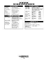
Page 57: ...of 45 or higher Diesel fuel according to ASTM 0975 ZEXEL Model VE Distributor o TDC Top Dead Center Throttle type Spin on type full flow Metal screen type 81 0 cfm 2 29 cmm COOLING SYSTEM Fresh water cooled block thermostatically controlled with heat exchanger 110 190 F 77 88 C Centrifugal type metal impeller belt driven Positive displacement rubber impeller beltdrivim 14 0 gpm 52 91pm measured be...

Page 58: ... 0 30 Hertz no load to full load 20 WI 60 Hertz 1800 rpm 120 Volts 166 Amps 120 240 Volts 166 83 Amps 161W 50 Hertz 1500 rpm 230 Volts 72 7 Amps General 3 Phase 20 0 WI 60 Hertz 16 0 WI 50 Hertz Voltage 3 Phase 60 Hertz Voltage 3Phase 50 Hertz Amperage 3Phase 60 Hertz Amperage 3 Phase 50 Hertz Brushless six pole revolving field Sealed lubricated single bearing design 12 Lead reconnectable for low ...

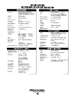
Page 59: ... higher Diesel lute according to ASTM D975 ZEXEL Model VE Distributor o TDC Top Dead Center Throttle type Spin on type full flow Metal screen type cleanable 94 6 cfm 2 7 cmm COOLING SYSTEM Fresh water cooled blotk thermostatically controlled with heat exchanger 110 19o F 77 as c Centrifugal type metal impeller belt driven Positive displacement rubber impeller belt driven 15 0 gpm 56 71pm measured ...

Page 60: ...ll load 3 Hertz no load to full load 20 KW 60 Hertz 1800 rpm 120 Volts 208 Amps 120 240 Volts 208 109 Amps 20 KW 50 Hertz 1500 rpm 220 Volts 87 Amps General 3Phase Voltage 3 Phase 60 Hertz Voltage 3Phase 50 Hertz Amperage 3Phase 60 Hertz Amperage 3 Phase 50 Hertz Brushless six pole revolving field Sealed lubricated single bearing design 12 Lead reconnectable for low voltage WYE and for Delta Solid...

Page 61: ...ystem Capacity fresh water FUEL SYSTEM Open flow self priming 1bleed point No 20 SAE J313 cetane rating of 45 or higher Diesel fuel according to ASTM 0975 ZEXEL Model PE In Line 12 BTDC Orifice type Full Row Replaceable Metal screen type cleanable 110 cfm 3 1 cmm COOLING SYSTEM Fresh water cooled block thermostatically controlled with heat exchanger 170 190 F 77 88 C Centrifugal type metal impelle...

Page 62: ...40volts 380 volts 220 volts 111 0Amps AC GENERATOR SINGLE PHASE Amperage 3Phase 60 Hertz 8 power factor High voltage WYE 48 1 Amps DELTA 96 2Amps General Single Phase Voltage Single Phase Voltage regulation Frequency regulation Rating Volts AC Brushless four pole revolving field Sealed lubricated single bearing design Reconnectable single phase for 120 240 volts with solid state voltage regulator ...

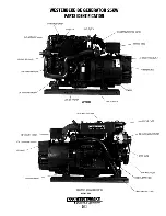
Page 63: ...E BE GENERATOR 20KW PARTS IDENTIFICATION EXHAUST ELBOW EXHAUST TEMPERATURE SWITCH o CONTROL PANEL AC CONNECTIONS OUTLET UNIT DATA TAG SENSOR LEFT SIDE L UNIT I D PLATE DC CHARGING ALTERNATOR RAW WATER PUMP STARTER WITH SOLENOID RIGHT SIDE Engines Generators 49 ...

Page 64: ...OIL PRESSURE SENDER 70 EXHAUST ELB OW HEAT EXCHANGER LED LEFT SIDE FRESH WATER FILL CAP DC BATTERY GROUND CONNECTION RIGHT SIDE Engines Generators 50 AC CONNECTIONS OUTLET IT DATA TAG LUBE OIL FILTER UNIT I D PLATE DC CHARGING ALTERNATOR LUBE OIL DRAIN HOSE STARTER WITH SOLENOID ...

Page 65: ...CER WATER INJECTED EXHAUST ELBOW EMERGENCY STOP SWITCH REAR CONTROl PANEl GENERATOR BACK END LED INDICATOR LIGHT HEAT EXCHANGER Oil Fill ENGINE OIL FilL CONNECTION TO IPHON BREAK LEFT SIDE Engines Generators 51 INJECTORS COOLANT PRESSURE CAP CONTROl PANEl CIRCUIT BREAKER REAR LINEAR ACTUATOR 10 NAME PLATE FRONT RAW WATER PUMP START MOTOR Oil SUMP ...

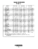
Page 66: ... 2 5 3 0 18 22 2 5 3 0 12 17 1 6 2 4 12 17 1 6 2 4 20 24 2 7 3 3 20 24 2 7 3 3 24 35 3 3 4 8 24 35 3 3 4 8 112 118 15 5 16 3 112 118 15 5 16 3 14 20 1 9 2 7 14 20 1 9 2 7 12 17 1 6 2 4 12 17 1 6 2 4 27 38 3 8 5 3 27 38 3 8 5 3 6 8 0 8 1 1 6 8 0 8 1 1 14 19 1 9 2 6 14 19 1 9 2 6 9 13 1 2 1 8 9 13 1 2 1 8 9 13 1 2 1 8 9 13 1 2 1 8 23 34 3 2 4 7 23 34 3 2 4 7 27 38 3 8 5 3 27 38 3 8 5 3 18 29 2 5 4 0...

Page 67: ...3 159 1 14 0 22 0 Grade 6T Grade 5 Cap Screw 6mm bolt head nut 1 4 3 6 5 0 6 0 9 1 4 UNC 9 11 1 2 1 5 8mm bolt head nut 1 25 10 8 15 9 1 5 2 2 1 4 UNF 11 13 1 5 1 8 1Omm bolt head nut 1 25 21 7 32 5 3 0 4 5 5 16 UNC 18 20 2 5 2 8 1Omm bolt head nut 1 5 19 5 30 4 2 7 4 2 5 16 UNF 21 23 2 9 3 2 12mm bolt head nut 1 25 ISO 36 2 57 9 5 0 8 0 3 8 UNC 28 33 3 7 4 6 12mm bolt head nut 1 5 36 2 50 6 5 0 7...

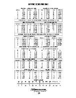
Page 68: ...56168 2 1 82880 7 6 40080 2 2 18723 7 7 65529 3 2 74320 8 7 31520 3 3 28084 8 8 74891 4 3 65760 9 8 22960 4 4 37445 9 9 84252 5 4 57200 10 9 14400 5 5 46807 10 10 93614 MOVE DECIMAL POINT FOR HIGHER VALUES e g 6 000 METERS 6 561 68 YARDS POUNDS TO KILOGRAMS KILOGRAMS TO POUNDS lb kg lb kg kg lb kg lb 1 0 454 6 2 722 1 2 205 6 13 228 2 0 907 7 3 175 2 4 409 7 15 432 3 1 361 8 3 629 3 6 614 8 17 637...

Page 69: ...rs two Spare Parts Kits each packaged in a rugged hinged toolbox Kit A includes the basic spares Kit B is for more extensive off shore cruising AKit Impeller Kit Heat Exchanger Gasket Fuel Filter with Gasket Oil Filter Drive Belt Zinc Anodes Fuel Lift Pump Filter Heat Exchanger End Gasket Clean out and inspect gasket at least once ayear Fuel filters orive Belts Inspect often look for cracking fray...

Page 70: ......

Page 71: ......

Page 72: ...1241 8 2017 ...

Reviews: