background image

Gasoline with an ETHANOL content 

higher than 10% (E10) is 

not allowed


and may void warranty.

Engines & Generators

Summary of Contents for 4.2 KW BCG-50Hz

Page 1: ...z 7 0KW BCGC 60Hz 5 9KW BCGC 50Hz 7 0KW BCGD 60Hz 5 9KW BCGD 50Hz GASOLINE GENERl R Single Phase NO 052020 FIRST EDITION MARCH 2005 r rWESTERBEKE member J WESTERBEKE CORPORATION 150 JOHN HANCOCK ROAD...

Page 2: ...Gasoline with an ETHANOL content higher than 10 E10 is not allowed and may void warranty Engines Generators...

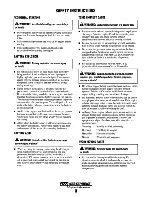
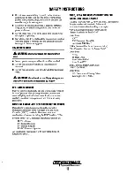
Page 3: ...EDIATELY Ifsymptoms persist seekmedicalattention Shut down the unit and do notrestart until it has been inspectedandrepaired A WARNING DECAL is providedby WESTERBEKE andshouldbe fixed to a bulkheadnea...

Page 4: ...r the carburetor fuel line filter fuel pump or other potential sources of spilled fuel or fuel vapors Use a suitable container to catch all fuel when removing the fuel line carburetor or fuel filters...

Page 5: ...skin or into the eyes inadvertently when removing electrolyte caps TOXIC EXHAUST GASES A WARNING Carbon monoxide CO is adeadlygas Ensure that the exhaust system is adequate to expel gases discharged...

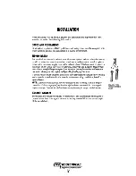
Page 6: ...with other cautions and notes to highlight critical information Read your manual carefully maintain your equipment and follow all safety procedures GASOLINE ENGINE AND GENERATOR INSTALLATIONS Prepara...

Page 7: ...on break when the exhaust manifold injection port is at or below the load waterline will result in raw water damage to the engine andpossibleflooding ofthe boat If you have any doubt about the positio...

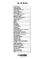
Page 8: ...Testing Relays 47 Testing the Igniter 48 Governor System Components and Operation 49 Panel Wiring Schematic 50 Electronic Governor Troubleshooting 51 Electronic Governor Models Prior to June 2004 52...

Page 9: ...IR BLEED PETCOCK FRONT PARTS IDENTIFICATION EXHAUST MANI FUEL FUEL FILTER LEFT SIDE Engines Generators 2 FILL DISTRIBUTOR I I __ THROTTLE CONTROL OIL DRAIN HOSE FILTER RAW WATER PUMP RIGHT SIDE CHARGE...

Page 10: ...e front end of the crankshaft NOTE To test engine compression see the ENGINE ADJUSTMENTsection ofthis manual OVERHAUL CONDITIONS Compression pressure tends to increase a little in a new engine until p...

Page 11: ...in plug 5 Loose oil pipe connector 6 Broken rocker cover gasket 7 Loose rocker cover attaching bolts OIL LEVEL RISING 1 Dead cylinder 2 Displaced ortwisted connecting rod 3 Worn piston ring 1 Incorrec...

Page 12: ...alve 3 Valve slem seized 3 Replace valve and valve guide 4 Broken valve spring 4 Replace valve spring 5 Compression leaks through cylinder head gasket 5 Replace gasket 6 Piston ring seized 6 Replace p...

Page 13: ...d Clean up all fuel and oilspills and properlydispose of the rags STARTER MOTOR HOUSING TYPICAL BC GENERATOR BACK END ASSEMBLY Unfasten the generator from its mounting rails or the mounting rails from...

Page 14: ...IONS thru out this manual Sealants and Lubricants Oil based PERMAlEX 2 and its HIGH TACK equivalent are excellent all purpose sealers They are effective in just about any joint in contact with coolant...

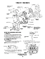
Page 15: ...uring an engine overhaul The adjustments inspection and replacement procedures may be performed without removing the generator from the boat THE TIMING BELT PART NUMBER IS 043036 Timing Belt Removal 1...

Page 16: ...ft in position NOTE Do not turn the crankshaft 2 Remove the crankshaft bolt Timing Bell Inspection Replace the belt if any of the following conditions exist HllI dening of the back rubber leaves no in...

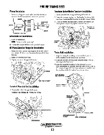
Page 17: ...ng Tensioner Installation 1 Install the tensioner spring and timing belt tensioner 2 Hook the tensioner spring onto the bend of the timing belt tensioner bracket and the stopper pin on the cylinder bl...

Page 18: ...the temperorarily tightened tensioner nut on the water pump side 1 or 2 turns and tension the belt making use of the spring force 8 Tum the crankshaft clockwise by nine camshaft sprocket teeth 81 to...

Page 19: ...TAT Loosen the raw water pump remove the drive belt and then remove the raw water pump RAWWATEfi PUMP FILTER FUEL FILTER ASSEMBLY Remove the fuel filter assembly Drain and inspect the hoses Inspect th...

Page 20: ...sher and insert Remove the rocker cover and rocker cover gasket Loosen each of the cylinder head bolts a little at a time so as to avoid the possibility of distorting the cylinder Repeat several times...

Page 21: ...worn replace the valve Check contact between the valve and valve seat by applying a thin coat ofPrussion Blue or Redhead on the valve seat contact face then insert the valve into the valve guide and...

Page 22: ...ing compound INSTALLATION Valve Stem Seal VALVE SEAT CONTACT WIDTH 035 051 in 0 9 1 3 mml Install the valve spring seat then using the valve stem seal installer install a new stem seal to the valve gu...

Page 23: ...Ibs 40 50Nm 3 Tighten the bolts in numerical order to the specified torque CYLINDER HEAD TORQUE 43 51fHbs 50 70Nm Rocker Cover Install the rocker cover using a new gasket slightly coat both sides wit...

Page 24: ...WEAR DAMAGE CHECKJOURNAL BEARINGS FOR WEAR DAMAGE Camshaft NOTE lfthe Journal is seized also check the cylinder head 3 Measure the cam height and if it is less than the limit replace the camshaft CAMS...

Page 25: ...7 0 6693mm II Or J OIL HOLES OIL HOLES INSTALLATION 1 Apply a coating of engine oil to the camshaft journals and cams and insert the camshaft through the rear of the cylinder head 2 Install the camsha...

Page 26: ...he ring remover remove the piston rings While removing the piston rings note the order they are removed and which side of the ring faces the piston crown 11 PISTON RING 111 PISTON RING 112 PISTON RING...

Page 27: ...80 0 04881n 1 22 1 24mm No 2 0 0476 0 04841n 1 21 1 23mm Oil 0 1108 0 1116In 2 815 2 835mm PISTON RING END GAP No 1 No 2 Oil PISTON Standard 0 0059 0 01181n 0 15 0 30mm 0 0138 0 01971n 0 35 0 50mm 0 0...

Page 28: ...it is seated on the bottom surface of the base Ifthe press fitting load is out of the specification replace the pin piston assembly or connecting rod or both PISTON PIN PRESS FITTING LOAD 1102 33071b...

Page 29: ...embly according to the identification marks for the crankshaft and the connecting rod CRANKSHAFT NO 3 NO 2 NO 1 r NO 1 ARM CRANKSHAFT PIN DIAMETER Identification marks 1 1 2 G 3 C Journal Diameter 1 4...

Page 30: ...nuts alternately to install the cap properly Tighten the nuts to the proper torque CAP NUT TIGHTENING TORQUE 11 90 turn 15Nm 90 turn A CAUTION If the cylinderheadhas been installed before installing t...

Page 31: ...and then use the special tool to break the pan seal IL PAN GASKET TOOL COUNTERBALANCE SHAFT REMOVAL 1 Remove the plug on the cylinder block and insert an 0 32in 8mm rod into the hole to lock the count...

Page 32: ...hould be no uneven wear on the contact surfaces of the cylinder block or on the pump gear side of the pump DRIVE GEAR FRONT CASE INSPECTION Check the front case for cracks or other damage also inspect...

Page 33: ...ont Case Assembly Install the front case assembly through the gasket and tighten the bolts to the specified torque FRONT CASE BOLTS TORQUE 6 7ft lbs 8 10 Nm There are two different length front case b...

Page 34: ...gainst the pump cover Oil Pump Seal Press the seal into the oil pump cover flush with the surface using the seal installer tool INSTALLING THE OIL PUMP SEAL OIL PUMP ASSEMBLY FRONT CASE CONFIGURATION...

Page 35: ...the journals contact surface for uneven wear and replace if badly damaged 2 Measure the outside diameter of the journal and the inside diameter of the main bearing If the clearance oil clearance exce...

Page 36: ...replace the case CRANKSHAFT BEARINGS SPECIFICATIONS Upper and Lower When the bearings are to be replaced select the correct ones and install them in positions according to the identification marks sta...

Page 37: ...AP BOLT TORQUE 36 40 ft Ibs SO 5SNm MEASURING END PLAY Push the crankshaft to the rear Then insert a feeler gauge in the gap between the crankshaftjournal side surface and the thrust bearing end surfa...

Page 38: ...ION CHECKING THE PISTON CLEARANCE Calculate the difference between the minimum cylinder bore in the thrust directitm and the piston outer diameter shown in the illustration If the difference exceeds t...

Page 39: ...6 565 6 580 Exhaust O 2571 0 2579 6 530 6 550 Stem to Guide Clearance Intake 0 0008 0 0020 0 02 0 05 0 0039 0 10 Exhaust 0 0020 0 0033 0 0050 0 0085 0 0059 0 15 Valve Guide Length Intake 1 73 44 Exhau...

Page 40: ...CRANKSHAFT BEARING Crankshaft End Play 0 0020 0 0098 0 05 0 25 Crankshaft Journal 0 0 1 5740 1 5748 39 98 40 0 Crankshaft Pin 0 0 1 4165 1 4173 35 98 36 00 Cylindericity of Journal and Pin Less than...

Page 41: ...Connecting Rod Camshaft thrust plate bolt 10 12 7 9 Connecting rod cap nut 15 90 turn 11 90 turn Rocker arm adjust nut 8 10 6 7 Crankshaft Bearing Cylinder Head Valve Oil seal case bolts 10 12 7 9 Cyl...

Page 42: ...ocket is loosened or tightened MD990767 VALVE SPRING COMPRESSOR MD 999597 SPECIAL TOOLS ENGINE NOTE These special tools are available from your local Mitsubishi Automotive Dealer VALVE STEM SEAL INSTA...

Page 43: ...elbow Once the engine has been re installed and running carefully check these assemblies and hose connections for leaks INSPECTHOSES REPLACE IF SOFT OR WORN ON THE ENDS HEAT EXCHANGER The heat exchang...

Page 44: ...and damage Inspect the weep holes for sign of water leakage and rust that would indicate a faulty seal The pulley should turn the shaft and impeller smoothly without noise or sluggish rotation The pul...

Page 45: ...n Reassembly 1 Install a new shaft seal 5 in the pump body Apply some glycerin to the lip of the seal 2 Install the circlip 13 on the shaft Support the outer bearing 18 and push the shaft into the bea...

Page 46: ...ge Adjustment Adjust the linkage so that when the choke solenoid is energized the choke butterfiy lever is open approximately 1 16 Adjust the linkage so the pin hole in the linkage is approximately 11...

Page 47: ...ISTRIBUTOR 3 COVER PICK UP ASSEMBLY VACUUM CONTROL 1 WIRE SET Cheek that when a screwdriver is passed near the iron core of the pick up assembly the needle of the tester deflects Adjust the point gap...

Page 48: ...wires and remove the solenoid from the motor Remove the thru bolts and screws from the back ofthe motor and separate the frame This will provide access to the brush holder assembly and the armature BR...

Page 49: ...he return stroke called pinion gap 3 If the pinion gap is not within the standard range 0 5 to 2 0 rom adjust it by increasing or decreasing the number of shims on the solenoid The gap is decreased as...

Page 50: ...ace it if the service limit is exceeded Also check the commutator outside surface for dirtiness and roughness Ifrough polish the commutator with fine crocus cloth Brush and Brush Holder Inspection 1 C...

Page 51: ...Pinion shaft end play adjustment Set the end play thrust gap to between 0 5 to 2 mm by inserting an adjusting washer between the center bracket and the reduction gear a Fit the pinion shaft reduction...

Page 52: ...WITCH REMOVE CUT OUT RES I STOR R6 ON OVERS PHD BOARi FOR OPERATION AT 1500 RPM 50Hz _ 0 START STOP o OVERspnD BOARD 12 II I IIIL t t _ t IBARBER COcE AN I CONTROl I ER 16 ORG i 16 WHT t 16 BLK 16 RED...

Page 53: ...ELAY DS s __ ____8 6 85_____________ L _ _ _ _ _ _ _ _J il __ di __ j CHOKE SOL ON START SWITCH SWITCH KI START RELAY l _ ____ jf __ j _____ _____ 86 8 5_____________ r L _ _ oJ I Io CKf2 I I I I I I...

Page 54: ...RED W I REMOTE PANEL WIRING SCHEMATIC 043912 REMOTE PANEL RED CKT 1L l ON SW WHITE WHITE Engines Generators 46 14 WHT RED 14 VEl RED 14 WHT 14 RED VIO VIEWED FROM MATING END...

Page 55: ...UNO i hJ i Irn eil GROUND AND 8 CONNECTIONS RELAYS o The relays used in the control system have coils which are polarized by the fact that they have internal free wheeling suppression diodes across th...

Page 56: ...below and read the meter Then reverse the ohmmeter leads and again read the meter In one direction the ohm reading will be 100 ohms less In the other direction there should be no ohm reading Any valu...

Page 57: ...n the power is tumed on and after it receives a signal from the magnetic pick Up it blinks at a faster rate GAIN ELECTRONIC SPEED CONTROLLER MAGNETIC PICK UP MPU INSTALLATION The MPU is installed in t...

Page 58: ...OVERSPEED PC BOARD PN 046732 MAGNETIC PICK UP MPU PN 046874 t c p WIRING SCHEMATIC 1 NOMINAL VOLTAGES at IDLE and 1800 RPM iH OVERSPEED PC BOARD PH 046490 I I illi j i 9 8 NOTE EWIRE ARE POLARITY SENS...

Page 59: ...ge between 9 and 8 between 11 and 10 Replace controller or as board as needed Unit starts runs at idle 1 Incorrect speed adjustments 1 Check and adjust speed adjustment NOTE Less than one volt DC 2 Fa...

Page 60: ...urn the GAIN potentiometer clockwise until the engine begins to hunt Ifthe engine does not hunt physically upset the actuator linkage 4 Tum the GAIN potentiometer counterclockwise until engine runs st...

Page 61: ...d the flywheel teeth the MPU may be damaged Remove the MPU and inspect it Replace if necessary and repeat the above installation procedure NOTE When replacing tlie Magnetic Pick Up MPU it MUST be repl...

Page 62: ...urple white stripe for the actuator connection The purple white lead is designated and is specific only in gasoline DC circuits a Actuator goes to full extension Diesel Does not retract Gasoline b Act...

Page 63: ...re to measure the compression pressurefor each cylinder Lookfor cylinders with dramatically at least 20 lower compression than the average ofthe other cylinders Ifthe weak cylinder is flanked by healt...

Page 64: ...the following timing specifIcations Timing Specifications 15 5 BTDC at 1800 rpm no load on generator IGNITION TIMING 7 VALVE CLEARANCE ADJUSTMENT NOTE Retorque the cylinder head bolts before adjusting...

Page 65: ...he belt and reduce the service life ofthe fresh water pump s bearing A slack belt or the presence ofoil on the belt can cause belt slipping resulting in high operating temperatures The BCGB generator...

Page 66: ...tor is first started the charger will produce a low chargillg rate This charging rate will rise as the generator is operated Fuse Protection A 30 amp fuse protects the windings from a failure of the b...

Page 67: ...Battery Capacity 105 Cold Cranking Amps CCA min Battery Charging Integral electric 17 amps General Fresh Water Pump Raw Water Pump Raw Water Flow Cooling Water Capacity Operating Temperature Fresh wa...

Page 68: ...tery Capacity 105 Cold Cranking Amps CCA min Battery Charging Integral electric 17 amps General Fresh Water Pump Raw Water Pump Fresh water cooled block through raw water cooled heat exchanger circuit...

Page 69: ...nd load check it with a portable meter and amp probe Generator Frequency Adjustment Frequency is a direct result of engine generator speed as indi cated by the following o When the generator is run at...

Page 70: ...relates to generator components A WARNING AC andDC circuits often share tlie same distributorpanel Be certain to unplug ACpower cords andshut down DC AC inverters Simplyswitching offcircuit breakers w...

Page 71: ...pair 4 0 2 0 EXCITER Each winding 3 9 2 5 CHARGE WINDING 0 08 0 08 INTERNAL WIRING SCHEMATIC r BRIDGE FUSE D I r I r I I r CHARGER I D O_DEfrJ b 0 U J I I I Low AC Output Faulty rotor winding A A I 6...

Page 72: ...ANCE VALUE 4 0 OHM TESTING THE ROTOR FIELD WINDINGS Unsolder the winding connection from the diode and care fully remove the diode from its isolated heat sink using a thin walled deep well 7116 llmm s...

Page 73: ...1 E42 and Ell E22 EW1 Exciter Windings 1 EW2 Exciter Windings 2 BCW Battery charging windings RW Rotor Winding C 1JCl Ell E21 E22 I _ EWl RW W1 W1 Stator Winding 1 W2 Stator Winding 2 C Capacitor D1 D...

Page 74: ...mount of petroleum jelly on the rotor bearing 0 ring located in the cover boss Position the cover onto the bearing and thread the allen head screws back into place finger tight Tighten the screws in a...

Page 75: ...BUNDLE THESE WIRES TO ACCESS THE WINDING FOR TESTING ON SWITCH lI4oI Alow resistance should be found with the leads in one direc tion and infinite resistance blocking in the other direction DIODES 1 4...

Page 76: ...RMAL AC VOLTAGE DURING 12 VDC EXCITATION 12 16 VOLTS AC 111 131 50Hz Cl Ellr iJ21 E31 E22 DUELEXCITER EW COLISEUM DUAL EXCITEIII MECC AlTE 60Hz 7 8 9 9 7 8 EW2 50Hz 1 1 2 0 C 3 0 1 4 T41 t42 121 5 0 t...

Page 77: ...erify a short to ground No continuity should be found between the two isolated stator winding groups W1 6 5 II I I I I I I I 411 l I 2 No reaction from the generator or drive engine No AC output This...

Page 78: ...er no load speed To do this Unplug all connections from the capacitor Locate the electrical connection for each winding end Place your AC volt meter connects across these two connections Start the gen...

Page 79: ...or is faulty The method above indicates a presumably good capacitor but does not verify it s microfared rating as would be necessary when troubleshooting a capacitor whose MF rating has dropped causin...

Page 80: ...Be GENERATOR COMPONENTS COLISEUM MODEL DIODE ASSEMBLY MECC ALTE MODEL Engines Generators 72...

Page 81: ...USE 0 1 STARTER e OIL PRESS SWITCH NIDI 2 IlLK u If N n l nr eu t DF WATER TEMPERATURE ill SWITCH IN C N BATTERY CHARGeR 20A DC CIRCUIT BREAKER 0 AUX OIL PRESS w SWITCH IN Ct FUSE SA Q I R 1 1 I ON SW...

Page 82: ...Shore PO lsr 120 VOLT 50 HERTZ TWO WIRE CONFIGURATION Generator I NOTE Diagram shows connections for a two wire 120 Volt system from the generator with three wlre 120 Voll boat system ll _ Ship to Sho...

Page 83: ...Drill Typ 4 holes Material Cold roiled Steel Lifting Eye Tool This tool allows a mechanic to safely remove the generator end from the engine by attaching this Generator End Lifting Eye to the four sc...

Page 84: ...C D on the face of each of the parts to be clamped This line should be an extension of the line A B COINCIDING LINE G 6 Draw another line F G on the face of each ofthe parts to be clamped This line w...

Page 85: ...402 545 568 770 1103 1495 1571 2130 1 8 590 800 660 895 910 1234 14 660 895 990 1342 M33 51 mm 546 740 774 1050 1500 2035 2139 2900 M36 55mm 700 950 992 1345 1925 2610 2744 3720 SEALANTS LUBRICANTS GA...

Page 86: ...g x 035 Ounces Pounds Ib x 454 Kilograms kg x 2 205 Pounds PRESSURE Pounds Per Sq In psi x 6 895 Kilopascals kPa x 145 p si Inches of Mercury Hg x 4912 psi x 2 036 Hg Inches of Mercury Hg x 3 377 Kli...

Page 87: ...125 17 85937 7 32 0 21875 5 55625 23 32 0 71875 18 25625 15 64 0 234375 5 95312 47 64 0 734375 18 65312 1 4 0 250 6 35000 3 4 0 750 19 05000 17 64 0 265625 6 74687 49 64 0 765625 19 44687 9 32 0 28125...

Page 88: ...le fc 1 0764 Lumens meter2 lm m2 Multiplv Fuel Performance By To oet eauivalent number of Miles qal mile qa 0 4251 Kilometers liter km Ll Gallons mile oal mile 2 3527 Liter kilometer Llkm Mult RJy Vel...

Page 89: ...d Bolts 56 Engine Adjustments 57 Terminal Board Connections 74 Engine Assembly 12 Testing Diodes 67 Engine Assembly General Data 6 7 Testing Engine Compression 55 Engine Troubleshooting 4 Testing for...

Page 90: ...Engines Generators WMDW6071120...

Reviews: