background image

Summary of Contents for FOUR-60

Page 1: ...ECHNICAL MANUAL AND PARTS LIST WESTERBEKE 1 5 hp i i Dies el Engine M ODEL FOUR 60 publication Numlter 16521 Edition 2 July 20 O WESTERBEKECORPORATION AVONINDUSTRIAL PARK AVON MA 02322 TEL 61 j58fJ 7100 ...

Page 2: ...ating filter elements at the time periods specified is a must and frequent checking for contamination i e water sediment etc in the fuel system is also essential Another important factor is the use of the same brand of a High Detergent diesel lubricating oil designed specifically for diesel engines The diesel engine does differ from the gasoline engine however in the method of handling and firing ...

Page 3: ...OUR 60 15 h p Mini Diesel Engine TABLE OF CONTENTS INSTALLATION DRAWINGS GENERAL DATA e INSTALLATION OPERATION LUBRICATION SYSTEM COOLING SYSTEM FUEL SYSTEM SAO TRANSMISSION SSL TRANSMISSION Page No 2 4 5 6 9 17 SECTION A SECTION B SECTION C 45 62 3 ...

Page 4: ... FUEL PUMP PRIMING LEVER RemOve after installation LIFTING BRACKET LUBRICATION OIL L FILLER CAP HEAT EXCHANGER BLEED SCREW SECONDARY FUEL FILTER BLEED SCREW FUEL INJECTOR UNION NUT COLD START GLOW PLUG FRESH WATER PUMP SEA WATER PUMP SEA WATER PUMP DRAIN ADJUSTABLE FLEX 10UNTS STARTER MOTOR PROPELLER SHAFT COUPLING STARBOARD AND PORT VIEWS FOUR 60 SAO ...

Page 5: ...ssion which was designed for the Four 60 Diesel The gear is available in two Ratios 1 3 1 and 2 1 Its small size and moderate offset greatly increases installability of Four 60 by de creasing length to 30 inches and reducing depth belowpropeller shaft line t04 3 4 inches 4A ...

Page 6: ... i ...

Page 7: ...INSTALL TION DRAWINGS 101 I 32 L DIRECT DRiVe I jo4 37 67 1 AND 2 1 RATIO Four 60 SAO Reverse and Reduction Gear 2 1 3o l 1 2 z o 16 1 _ _ _ _ _ _ 343 _ _ I Four no SSLReverse Gear 5 ...

Page 8: ...s Camshaft drive Injection pump drive Injection pump chain wheel bearing liner 6 Inside diameter finished in position Clearance on hub 4 23 6 1 2 477 to 2 4785 in 62 915 to 62 94i nun 3 0 in 76 2 mm 57 9 cu in 948 c c 600 r p m 2 750 r p m _ 2 500 r p m 38 lb ft 5 32 kg m at 1 750 r p m 0025 to 0045 in 062 to 113 mm 0015 to 0035 in 038 to 097 mm 0015 to 0035 in 038 to 097 mm 010 to 015 in 2S4lo 38...

Page 9: ...Rocker shaft to bush clearance Tappet diameter 5615 to 5625 in 14 263 to 14 288 mm 0005 to 002 in 013 to 051 mm Flywheel and starter ring Number of teeth on starter ring Starter ring fitting temperature Oil pump Rotor end float Rotor lobe clearance Oil pressure relief valve Spring free length Spring fitted length Load to compress spring to fitted length Oil pressure Idling speed Normal running spe...

Page 10: ...gs Cylinder head nuts Injector clamp nuts Rocker bracket nuts Flywheel bolts Main bearing bolts Connecting rod bolts Injector nozzle nuts B lectrical ystem Nominal voltage Battery NOT supplied with engine Terminal voltage Recommended capacity Generator Capacity Voltage Alternator optional Capacity Voltage TRANSMISSIONS Four 60 Gear Options 60 ft lbs 15 ft lbs 25 ft lbs 40 ft lbs 70 ft lbs 35 ft lb...

Page 11: ...R ENGINE ENGINE BOLTS PROPELLOR COUPLING ALIGNMENT EXHAUST LINE INSTALLATION ENGINE COOLING SYSTEM FUEL PIPING FUEL SUPPLY CONTROLS ELECTRICAL SYSTEM PREWIRING AND OPTIONS STARTING AID INSTALLATION Page No 10 10 10 11 11 11 11 12 12 12 13 14 14 1 5 9 ...

Page 12: ...tage or damage is noted file claim with the agent before accepting shipment reporting same to the shipper FOUNDATION FOR ENGINE A good engine bed contributes much towards the satisfactory operation of the engine The engine bed must be of rigid construction and neither deflect or twist when subjected to the engine weight or the position the boat mCl Y have to take under the effects of rough seas Th...

Page 13: ... when the shaft can be slipped backwards and forward into the counter bore with no interference and when a feeler gauge indicates that tlie flanges come together at all points The two halves of the coupling should be parallel within O 001 mch if possible However the maximum allowable tolerance must not exceed 0 001 inch per inch of coupling O D In making the final check for alignmellt the engine h...

Page 14: ...g is secured by m eans of copper straps The final connection to the eng e should be through the flexible rubber hoses supplied FUEL SUPPLY see Fig 2 for Fuel inj ction P t imp lever control positions To ensure satisfactory operation a Diesel engine must have a dependable supply of clean fuel oil For this reason cleanliness and c are are especially import ant at the time when the fuel tank is insta...

Page 15: ...ual Anchor points must be securely fixed to rigid member so that effort put into the clutch handle reaches the clutch cross shaft without lost motion With rod and lever installations it is desirable to maintain balance among the several members so that the weight of components does not tend of itself to pull the clutch lever from neutral position towards either Ahead or Astern SSL Transmission may...

Page 16: ...heat function and two 6 conductors for the ammeter Chief advantages are pre wiririg will be e imination of wiring mistakes and minimum installation time The cables are 10 foot lengths to accommodate all installations 2 All Electric Panel The Westerbeke all electric panel utilizes an electronic tacho meter with a built in hour meter Tachometer cables are no longer required The panel is anodized alu...

Page 17: ...J START MOTOR I SOLENOID rOIL PRESS sw OPTIONAL Fig 3 Wiring Diagram with Generator and Skipper Panel WESTERBEKE ALL ELECTRIC PANEL WITH ALTERNATOR ONLY LAMPS OIL PRESS SENDER WATER TEMP SENDER ENGINE KEY SWITCH PANEL r F 1 10 0 RUN I 1 6 SATTERY IZVDC START I 1 I I I I PREHEAT I SW I 16 I 10 I L _____________J BATTERY CA8L E OIL PRESS SW OPTIONAL Fig 4 Wiring Diagram with Alternator and Electric ...

Page 18: ...ypass this resistor and connect the glow plugs directly across the battery while cranking It is most important that the glow plug circuit be wired correctly to prevent burn out of the glow plugs and provide battery charging To start the engine depress the glow plug PRE HEAT pushbutton for 30 seconds or longer depending upon clj matiG conditions and then engage the START switch Both pushbutton and ...

Page 19: ... AFTER INSTALLATION BLEEDING THE FUEL SYSTEM TO START ENGINE WHEN ENGINE STARTS TO STOP ENGINE OPERATING PRECAUTIONS COLD WEATHER PRECAUTIONS POST DELIVERY CHECKOUT NTENANCESCHEDULE END OF SEASON SERVICE Page No 19 19 20 20 21 21 22 22 23 23 17 ...

Page 20: ... A E DESIGNATION COMPANY BRAND OO 45 F 45 80g F OVER 80 F Ameri can 0 1 Co American Supermil Motor Oil lOW 20W 20 30 BP Canada Limited I BP Vane11us lOW 20W 20 30 i I BP Vane11us 10W 30 10W 30 10W 30 Chevron Oil Co I RPM DELO Multi Service Oil lOW 20W 20 30 I Cities Service Oil Co I CITGO Extra Range lOW 20W 20 30 I Continental Oil Co I CONOeO TRACON OIL lOW 20W 20 30 I Gulf Oil Corporation I Gulf...

Page 21: ...tery water level is at least 3 8 inch above the battery plates and battery is fully charged so that it is capable of the extra effort that may be required on the first start 5 Fill fuel tank with clean Diesel fuel oil No 2 diesel fuel oil is recom mended The use of No 1 i s permissible but No 2 is preferred because of its higher lubricant content NOTE If there is no filter in the filler of the fue...

Page 22: ...e crankshaft if battery is charged and the engine is getting fuel The cranking motor turning over fast indicates the battery is charged If battery is charged and engine doesn t start check fuel system as follows a Ensure the fuel valve between tank and engine is open b Ensure the fuel STOP RUN control lever is in the full RUN position at the stop control lever on the injection pump c Check for lea...

Page 23: ...tes every half hour to accelerate oil circulation and thus to eliminate conditions favorable to sludge and carbon formation 8 Reverse Operation Always reduce Ilgine to idle speed when shifting gears However when the transmission is engaged it will carry full engine load NOTE The SAO transmission requires that when backing down ttte snift lever must be firmly held in the reverse position since it h...

Page 24: ...er and when coolant free of air bubbles issues from this vent point replace and tighten vent screw Fill the expansion tank to within one inchfrom top of tank Start engine and run engine for 3 or 4 minutes Stop engine and add coolant as necessaryo NOTE The strength of the anti freeze solution must be maintained by topping off with the solution as necessary 4 Fuel filters must be checked more often ...

Page 25: ... oil filter gasket for leaks Check oil sump level This is important as it may be necessary to add oil to compensate for the oil that is required to fill the engine s internal oil passages and oil filter Add oil as necessary 5 Change oil in transmission Use SAE 30 High Detergent Lubricating Oil Service DG DM or DS Do not overfill 6 Clean Air Filter NOTE The time period for replacing the air filter ...

Page 26: ...roofed adhesive tape or some other suitable medium 6 Seal the exhaust outlet at the most accessible location as close to the engine as possible 7 Remove injectors and spray into cylinder bores 1 8 pint of lubricating oil divided between the cylinders 8 Replace injectors with new sealing washer under each injector Turn engine slowly ov r compression 9 Top off fuel tank completely so that no air spa...

Page 27: ...lve Oil pump Oil pump drive Oil strainer Pistons Sump Tappets Timing chains Timing chain tensioners Timing chain wheels Tractometer drive Valves Valve rocker clearance adjusting Valve rocker shaft Valve seat reconditioning Valve timing check SECTION A DIESEL ENGINE Section 1 9 A 16 A 12 A ll A 8 A 17 _A IO A 9 A IO A 2 A 3 A S A 4 A 6 A II A 12 A II A 7 A 9 A 9 A 9 A 6 A 8 A I3 A 7 A IS A I4 A A I...

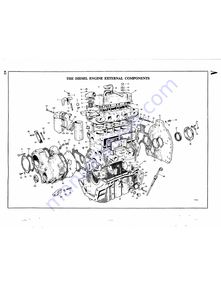
Page 28: ...III II 1 1 1 1 III 1 11111 11111 11 1 1 1 111 1 J 11 111 1 11 1 1 1 11 W 97 89 aa 87 90 91 THE DmSEL ENGINE EXTERNAL COl fPONENTS 13 3 g 7 4 Wo 5 t 12 9 It 1 tf 98 6 83 81 G 86 85 84 IS 38 I PII34 I 0 _ _ _ ____ J ...

Page 29: ...late SO Joint washer for top fixing hole of front plate 81 Timing indicator for injection pump 82 Timing cover 83 Joint washer for timing cover 84 Vibration damper camshaft chain 85 Bolt for vibration damper 86 Lock washer for bolt 87 Vibration damper injection pump chain 88 Stud for vibration damper 89 Nut for stud 90 Lock washer for nut 91 BoIt for timing cover 92 Nut for bolt 21 Joint washer fo...

Page 30: ...2 III 120 l 23 120 8 I O6 100 10 4 lOS 22 119 rIO I f 1i lf 21 1I0i 112 1J 1 5 03 14 I O_A 109 101 I IS 1l lI 1 3 15 117 IO TJ i o l 102 90 92 1 70 116 l g 93 91 K I e d 95 9 4 16 f6 53 56 f 1 1 11111111 I 1II III It 11 1 1 11 II 11 1 I 11 1 11111 1 II 0 __C _ ...

Page 31: ...p drive Valve spring outer 60 Bolt flywheel to crankshaft l00 Chain tensioner body camshaft drive Valve spring inner 61 Lock washer for bolt 101 Chain tensioner cylinder Valve spring collar top 62 Dowel clutch to flywheel 102 Chain tensioner spring Valve cotter 63 Key for crankshaft 103 Chain tensionerslipper head Spring clip for valve cotter 64 Crankshaft chain wheel camshaft drive 104 Chaintensi...

Page 32: ...A 1111 11 I t I I i i I i I I I I i i i I I 4 6 I 11111 III 1111111 1111111111 THE ENGINE Longitudinal Section If 1111 I III III I f I It II J J 1111111111 1 ...

Page 33: ...I I i i i I i f i i I I 1111111 111 11111 111111 1111 1111111111111 111111 11111111111 111 1111 11 1 1111111 fI I 11I1 IIIIU THE ENGINE Transverse Section A I 1 i A7 ...

Page 34: ...1 II 11 1 11 1 III I 1111111 I III I III 1 1t II I I I I 11111 I II III I II I 111111 I I I I I I I 00 Z 0 U 1 4 I f i Z 1 4 Z I I i i I t I 1111 11111 1111 J III 1111 11 1 111111111 1111 1111 II I III a III II 1111 I III I 1111 ...

Page 35: ... bores Oil is fed to the camshaft bearings through passages from the main bearings A passage from the camshaft centre bearing feeds oil to the camshaft skew gear and a drilling from the camshaft front bearing supplies oil to the cylinder head where further drillings lead to the rocker shaft via the front rocker support bracket The oil from the rocker gear drains down the push rod tunnels to the su...

Page 36: ...alve seating by appJying engineer s blue to the conical valve face and testing for continuous marking If necessary lap the valve onto the seat using tool 18G 69 Refitting 6 Reverse the procedure in I to 3 ensuring that the cap nut washer is in a serviceable condition Section A 6 TRACTOMETER AND OIL PUMP DRIVE SHAFT Removing l Unscrew the centre bolt and remove the oil filter bowl and element 2 Dis...

Page 37: ...d Ifthe bushes areworninforged rockers theyshould be renewedusing tools 18G 226 and 180226 A Fit new blishes with the butt joint positioned at the top of the rocker bore and drill oil holes in Fig 4 4 The pressed steel type of valve rocker which should not be rebushed Fig A S Fitting a valve rocker bush U ing tools 18G 226 and18G 226 A each bush to coincide with the oil ways in the rocker If the h...

Page 38: ...e the two nuts and washers securing the exhaust manifold and the six nuts and washers securing both air and exhaust manifolds and lift both manifolds away 22 Remove the spill pipe and clamps from the in jectors and withdraw the injectors from the cylinder head using tool 18G 284 and adaptor 18G 284 P 23 Unscrew the three nuts and remove the water outlet elbow Ease the outlet elbow gasket off the t...

Page 39: ... of the valves should stand below the cylinder ead face A 018 to 038 in 46 to 97 mm Fig A 9 Cylinder head nut tightening sequence Section A 9 CAMSHAFT TIMING GEAR AND ENGINE FRONT PLATE Removing Timing cover 1 Remove the radiator Section B 3 1 to 10 2 Remove the hydraulic pump drive belt 3 Remove the dynamo and drive belt Section K 5 2 to 5 4 Remove the water pump Section B 4 3 to 5 5 Unscrew the ...

Page 40: ...also be carried out but is not neces sary 29 Disconnect and remove the oil pipe from between A l4 the chain tensioner packing block and the injection pump chain wheel hub 30 Remove the injection pump Section C 6 1 to 3 31 Remove the chain wheel hub from the front plate Inspection 32 Examine the crankshaft front oil seal and renew it if there is the slightest sign of wear or damage 33 Check both ch...

Page 41: ...he plunger peg Still holding the assembly closed refit and lock the plug in the base of Fig A 12 Showing the positions oj the timing marks when the timing gear is correctly assempled 1 Injection pump driving flange 2 Injection pump chain wheel 3 Crankshaft chain wheel injection pump drive 4 Crankshaft chain wheel camshaft drive S Camshaft chain wheel Fig A 13 Using too 18G 3 to centralize the timi...

Page 42: ...to 28 11 Unscrew the connecting rod cap bolts remove the caps with their bearing halves and push the con necting rods up the cylinder bores Connecting rods and caps should be marked to ensure refitting in their original positions 12 Remove the main bearing cap bolts caps main bearing bottom halves and the two half thrust washers positioned on the faces of the centre cap The main bearing caps and t...

Page 43: ...te Section A I0 2 to 4 8 Remove the sump Section A 11 S 9 Remove the rocker shaft and push rods Section A 7 1 to 5 10 Remove the cylinder head Section A S 6 to 9 11 and 12 14 and 15 and 17 to 19 11 Unscrew the connecting rod cap bolts remove the caps with their bearing halves and withdraw the connectin g rods and pistons fro the top of the cylinder bores The connecting rods and caps should be mark...

Page 44: ...e following points A I8 a Position the clutch driven plate as described in Section D 2 40 b and c b Adjust the clutch pedal free movement as des ribed in Section D 1 1 to 3 c When connecting the stop control cable to the injection pump ensure that the stop lever on the pump has its full range o fmovement 26 Refit the front axle and radiator by reversing the procedure in Section 0 1 2 to 7 and Sect...

Page 45: ...axiniu D radius 015 in 381 mm J 4So K 30 Exhaust B L 1 0375 to 1 0385 in 6 352 to 26 377 mm M 916 to 921 in 23 266 to 23 393 mm N 812 5 in 20 638 mm P 070 to 075 in 1 78 to 1 9 min Q 258 to 261 in 6 55 to 6 63 mm R Maximum radius 015 in 381 mm s 45 T 20 Fig A l9 Recu ting a valve seat with tools t8G 27 18G 167 and 18G 167 D Cut new valve seats in the inserts to the dimensions given in Fig A IS and...

Page 46: ...iner using tool 18G 124 A and adaptor 18G 124 K The inset shows the liner being replaced 1 Slotted washer 2 Slotted washer 3 D washer 4 Adaptor 18G 124 K Centre bearing liner 15 Insert pilot adaptor 18G 214 K into the front bearing liner from inside the crankcase 16 Place the new centre bearing liner on the small diameter of adaptor 180 124 B and insert the adaptor large diameter first into the ce...

Page 47: ... centre bearing liner 29 Release the cutter and withdraw the arbor Section A 17 CYLINDER LINERS The cylinder liners may be bored out to a maximum oversize of 020 in 51 mm If the liners will not clean up at this figure remove them through the top face of the cylinder block using either specialized proprietary equipment or a power press and a set of adaptors made as shown in Fig A 22 The necessary p...

Page 48: ......

Page 49: ... the fresh water closed circuit and finally into the engine exhaust for over board discharge In order that the engine will reach its operating temperature as quickly as possible a thermostat fitted to the cylinder head will open to allow circulation in the closed circuit when the coolant temperature has reached 1750 F SEJ WATER PUMP Fig B1 This is a self priming positive displacement rotary pump w...

Page 50: ...pressure must be released gradually when the filler cap is removed 1 Turn the cap slowly anti cloGkwise until the resistance of the safety stops is felt 2 Leave the cap in this position until all the pressure is released 3 Press the cap Qbwnwards against the spring to clear the safety stops and continue turning until it can be lifted off Open the cylinder block drain tap located on the left hand s...

Page 51: ...e in the pump body and tap out the spindle and bearing assembly 8 Withdraw the vane from the spindle using an extractor and remove the water seal 1 By pass adaptor 2 Washer for by pass adaptor 3 Water pump adaptor 4 Joint washer for pump adaptor 5 Set screw for pump adaptor 6 Joint washer for pump body 7 Vane 5 6 F r B 5 9 IO Water pump omponents 8 Seal 9 Set screw for lubricating point 10 Fibre w...

Page 52: ...into the pump body Ensure that the hole in the bearing coincides with the lubricating hole in the body and fit the bearing locating wire and the water seal 12 Press the vane onto the spindle until its face is flush with the face of the body see Fig B 4 13 Press the pulley hub onto the spindle to the dlmenslon shown m Flg B 4 REFITTING 14 Reverse the procedure in 2 to 5 and fill the cooling system ...

Page 53: ...c SECTION C FUEL SYSTEM DIESEL MODELS Altitude settings C IO Filter main CoS Injection pump C 6 Injectors C 7 Lift pump CA Maximum and idling speed adjustment C 9 Tap C 3 C l ...

Page 54: ...9 69 1ill J 13 P L ft i 6 9 20 22 68 __ n 74 5 JI 64 it 57 58 59 60 61 65 Z I 4 56 c1J 48 _ ff 63 52 I 3 I 1 2 49 r 53 62 30 55 1 50 31 23 35 34 38 40 42 44 45 9 9 7 51 __ _ _ _ _ c J 32 I I J I I 1 L al L O _ tli3 i I U I ii I I c J6 ii J l 29 26 24 25 33 36 37 cO 39 41 43 IIL JS III 19 c 27 28 j 1 119 126 120 IJ IJ 1I00 __ d 1I4 125 124 Jl3 128 9 fi J I 100 104 103 102 105 6 6855 11 1 IIII H I I...

Page 55: ... Linkage nut 105 Quill shaft 20 Transfer pump rotor 63 Keep plate 106 Cover plate 21 Transfer pump vanes 64 Control cover stud 107 Gasket for cover plate 22 Transfer pump liner 65 Tab washer for stud lOS Screw for cover plate 23 Hydraulic head and rotor assembly 66 Nut for stud 109 Washer for screw 24 Rotor plug 67 Washer for nut 110 Advance unit housing 25 Washer for plug 6S Throttle shaft 111 Ga...

Page 56: ...OWNERS NOTES ...

Page 57: ...r location purposes during re assembly 5 Slacken the clamp screw and remove the pump filter bowl 6 Withdraw the bowl sealing ring and the filter gauze from the pump cover 7 Remove the five screws and separate the cover from the pump body S Press the centre of the diaphragm lightly down wards and rotate it through 90 to disengage the pull rod from the operating link Withdraw the diaphragm assembly ...

Page 58: ... 3 Unscrew the centre bolt in the filter head and detach the base from the filter 4 Separate the filter element from the filter head 5 Remove the sealing ring from the filter base and the sealing ring and 0 ring from the filter head 6 Remove the non return valve from No 3 in1et connection and the sealing plug from No 4 outlet connection in the filter head Inspection 7 Examine the filter head and b...

Page 59: ...l lSG 659 and using spanner lSG 634 slacken the transfer pump rotor by turning it in the direction of pump rotation as shown on the pump nameplate 20 Remove the two hydraulic head locking screws one of which incorporates an air vent valve and withdraw the hydraulic head and rotor assembly from the pump Remove the 0 ring from the groove in the periphery of the hydraulic head 21 Unscrew the transfer...

Page 60: ... for signs of wear Reassembling Rinse the components in clean Shell Calibration Fluid C and assemble them wet 38 Fit a new drive hub oil seal to the pump housing using tool18G 663 Insert inspection plug 18G 660 into the oil seal and examine the oil seal a con tinuous black line should be visible through the plug 39 Fit the two washers into the drive hub and insert the hub into the hub oil seal 40 ...

Page 61: ...s the contour of the roller shoe ears 47 Insert the rotor assembly into the hydraulic head then fit and lightly tighten the transfer pump rotor 48 Stand the head and rotor assembly on the bench drive plate uppermost Fit the relief valve timing adaptor 180 653 A preset at J 5 atmospheres to high pressure outlet V on the hydraulic head and connect this assembly to testing machine 18G 109 A see Fig C...

Page 62: ...bolt using protection cap 18G 639 Position the non return valve ball in the side ofthe head locating bolt and fit the bolt to the advance unit Using assembly cap 180647 fit anew inner 0 ring to the shank of the locating bolt and place the plain washer on top of the 0 ring 58 Place a new advance unit joint washer on the pump housing with the straight side of the D shaped hole at the drive end ofthe...

Page 63: ...t is not less than 1 000 c c min Ifthis flow cannot be obtained a maximum feed pressure of 2 lb sq in 15 kg cm 2 is permissible c Do not run the pump for long periods at high speed with low fuel output el Do not run the pump for long periods with the shut off control in the closed position e Ensure that the throttle and shut off controls are in the fully open position except where stated otherwise...

Page 64: ...et the end plate adjuster to give an advance gauge reading of 21 Test 5 Advance position Increase the pump speed to 1 400 r p m The advance gauge reading should now be 3 to 41 Test6 Back kakage Run the pump at 1 000 r p m and measure the back leakage in the measuring glass it should be 5 to 50 C c per 100 shot time cycle Test 7 Maximumfuel delivery Run the pump at 1 000 r p m The average delivery ...

Page 65: ...iming mark on the fuel infection pump flange using toollSG 648 A Test 14 Timing setting Refitting After the foregoing tests have been completed remove the pump from the test bench and mount flange marking gauge lSG648 A preset to 84 on the pump quill shaft Using testing machi ne 180 109 A alia timing adaptor ISO 653 A apply 100 atrnospheres pressure to outlet V in the hydraulic head while rotating...

Page 66: ...l Calibration Fluid C 9 Examine the spring for signs of weakness rusting or fraeture and ensure that the ends are perfectly square Check the spindle for straightness 10 Ensure that the face of the nozzle holder which contacts the nozzle is perfectly smooth and fiat 11 Using cleaning kit 180487 thoroughly clean the nozzle body and valve C l4 Fig C 20 Clearing the pintle orifice Fig C 21 Cleaning th...

Page 67: ...II 9 Fig C 26 C 2 3 4 5 ____1 11111 6 7 Section through a fuel injector 1 Injectpr cap nut 2 Joint washer 3 Locknut 4 Joint washer S Nozzle holder 6 Nozzle nut 7 Nozzle body 8 Nozzle vaJve 9 Spindle 10 Spring 11 Washer t2 Spring cap nut stepped and should be free from scores and pitting 16 Examine the conical surface which forms the seat of the nozzle valve through a nozzle microscope The most cri...

Page 68: ... stages of lapping this surface may be narrow or have a bright circumferential ring These markings indicate the extent of the wear on the nozzle seat 24 Reface the lap as described in 19 after every 1t minutes of lapping time 25 When the seat appears satisfactory after a few seconds lapping with a freshly ground lap use fine lapping paste to finish the seat off to a smooth mat surface Lapping shou...

Page 69: ...just the spring cap nut to give an injection pressure of 170 atmospheres Fig C 30 Testing an injector for Jpray using testing machine 18G 109 A and adaptor 18G 10 B Fig C 31 Reassembling a fuel injector using fixture 18G 388 spanner 18G 210 and torque wrench 18G 372 37 Operate the pumping lever until the pressure gauge registers 160 atmospheres Release the lever and time the pressure drop from 150...

Page 70: ...nd fitted C 18 1 Ensure that the stop control is fully home in the run position and remove the sealing cap from the maximum speed stop screw 2 Run the engine until it bas attained its normal running temperature 3 Slacken the locknut and adjust the maximum speed stop screw to set the engine maximum light running speed at 2 750 r p m This will give the engine a maximum governed speed under load of 2...

Page 71: ...EAR HOUSING ASSEMBLY FROM ENGINE REMOVAL OF GEAR CASE ASSEMBLY FROM REV ERSE GEAR HOUSING DISASSEMBLY OF GEAR CASE INSPECTION ASSEMBLYOF GEAR CASE ASSEMBLY OF REVERSE GEAR CASE IN REVERSE GEAR HOUSING ASSEMBLE TRANSl llSSION TO ENGINE ASSEMBLY OF REDUCTION GEAR ASSEMBLY TO REVERSE GEAR HOUSING ASSEMBLY ADJUSTMENTS REDUCTION UNIT Page No 46 46 46 46 48 51 51 52 53 53 55 56 56 57 59 45 ...

Page 72: ...ing the boat in either direction It is recommended that the shifting be done at speeds below 1000 RPM and prefer ably in the 800 RPM range or lower to prolong the life of the engine transmission and of the boat TROUBLE SHOOTING The trouble shooting charts below and on the next page shoUld be studied and the suggestions carried out prior to any disassembly to determine as well as pOGsible what the ...

Page 73: ...ine gear bearings worn exce55ively causin misalignment of engine shaft Re place necessary parts Check misalignment of engine gear 4 Over adjustment of eit her forward and reverse or both will result in loss of neutral Check and readjust as outlined under adjustment GEAR SLIPPING OR SLOW TO ENGAGE WITH SHIFT LEVER IN FORWARD OR REVERSE T I Check For 1 T I 3 WORN REVERSE BAND I 1 WORN CLUTCH PLATES ...

Page 74: ...t or dama gcd linkage parts Replace defective llIuu rial Improper forward clutch adjustment djust forward dutch as outlincd under adjustment 5 Check for broken output shaft Replace d fective shaft NOTE Disassembly need be carried out only as far as is necessary to correc t those difficulties which interfere with proper marine gear operation REMOVAL OF REDUCTION GEAR ASSEMBLY FROM REVERSE GEAR HOUS...

Page 75: ...n en en CD n J C 0 rj 0 h o 1 fl I I 1581 f t i fl A IJ lJ A 1V Ul4V lln tzJ N 1 1 ___ 0 fi J c i i c n I C V 0 t 4 s 0 Z Ci CD 42 J ZM qy V 1 I t it If W Pol 1 en 0 s r sT I I aI I 0 z t 4 U JU 44 72 UJ 0 co ...

Page 76: ...CI I o 65 67 25 l2 ta 19 27 6 D ECr O V SAOD 94 1 r 8 l H 0 FW 6 i I I H 0 2 2S DI r L II21 w rr l2 s Y WIll ...

Page 77: ...nd as sembly 62 Remove lock spring 3 Remove adjustment nut 66 fro m reverse cam 65 Remove reverse cam 65 from eye in yoke 34 and slide out reverse cam 65 from reverse cam slide assembly 63 4 Remove cross shaft 13 from reverse gear housing 3 as follows 5 6 7 8 9 10 a Loosen the two capscrews securing the yotte 41 to the cross shaft 13 b With small end of housing toward m echanic slide cross shaft 1...

Page 78: ...sher 6 and thrust washer 16 1 from end of tailshaft on direct drive units 2 Remove lockscrew 55 and lockwasher from screw collar 53 and remove screw collar from gear case by unscrewing Lift operating sleeve assembly 50 from tailshaft when removing screw collar 3 Lift pressure plate 49 and clutch plates 48 and 54 from erd of gear case 4 Properly support gear case on clutch plate carrier and press t...

Page 79: ...or wear from reverse band linking short or long pinions wearing into inside faces or wear in clutch plate slots on threaded end 14 Screw collar and finger assembly should be examined for wear 15 Pressure plate should be examined for wear 16 All old gaskets should be replaced 17 Operating sleeve assembly should be examined for wear 18 Engine gear should be examined for wear on oil seal surfaces cas...

Page 80: ...haft and press tailshaft through pro peller gea r until propeller gear is seated against the clutch plate carrier already on tailshaft Support the entire assembly on propeller gear inside front end of gear case during pressing operation 7 Place Woodruff key 61 on end of tailshaft inside propeller gear 8 Install clutch plates in clutch plate cavity in rear of gear case starting first with bronze cl...

Page 81: ...d secure with necessary bolts 9 Install reduction gear crescent 74 10 Tighten all capscrews Tighten reverse gear tailshaft nut 18 2 until cotter pin can be installed through castellation in nut and hole in reverse gear tailshaft 11 Install cotter pin and bedn ends over nut 12 Place new gasket 72 on reduction adapter plate 85 13 Install brake band assembly 62 onto gear case assembly 41 ip reverse g...

Page 82: ...gine gear I into flywheel housing damper spline c Align mounting holes in front end plate 5 with holes in flywheel housing and secure with lockwashers and capscrews d After installing on engine check engine gear for runout Ma imum eccentricity is 005 inches at pilot roller bearing 2 Insert two studs three inches long in two opposite bolt holes in front end plate 5 3 Check to be certain that pilut ...

Page 83: ...verse 4 Replace gasket 4 cover 10 and secure to reverse gear housing witt capscrews and cover seals The transmission is ready for a prelimlnary test which may be done at dockside 5 Check all of the mooring lines before continuing the test 6 With the engine running at idle speed shift the transmisslon into forward and reverse noting how well the transmission responds 7 If the transmission does not ...

Page 84: ...djoining it in the screw collar Then rotate the screw collar to the right until the next hole in the pressure plate is lined up under the dog of the lockscrew Make certain that the lockscrew enters the hole properly or it will bind up the forward clutch When the transmission is properly adjusted replace the cover and secure all external bolts and fasteners Before replacing the shifting linkage che...

Page 85: ...gear half coupling and pressag ilnst shaft to force coupling from assembly 5 Support reduction gear housing so that flanged shaft assembly can drop free approximately 2 inches and press flanged shaft assembly from reduction gear housing 6 Remove retaining ring 76 from groove next to ball bea 1g 84 inaide reduction gear housing and press ball bearing from housing 7 If necessary to replace remove oi...

Page 86: ...r 73 is seated against ball bearing 84 in reduc tion housing 10 Support unit on inside of flanged shaft with large end of unit down and press gear half coupling 75 onto shaft end and into ball bearing until coupling is seated against ball bearing Care must be taken to line up keyway in coupling and key in shaf before pressing together 11 Place lockwasher 78 over end of flanged shaft with tang on i...

Page 87: ...o a left hand engine and turns a right hand propeller It is available in two ratios ModelSSL 13 Model SSL 20 1 3 I Ratio 2 I Ratio It is differentiated from the Model SSR 20 For right handed engines by having the clutch lever on the left hand side It is also notable that when fitted to Model Four 60 the water pump is omitted from the high speed shaft of the transmission 61 ...

Page 88: ... Four 60 2 Remove Woodruff key from reverse gear engine shaft 3 Remove four capscrews securing front end plate 1 to housing 4 Remove front plate 1 containing bearing 16 snap ring 17 seal 18 bearing 23 Protect seal by tape over key slot in shaft 5 Lift out shaft 15 which has pu p shaft 22 screwed into rear end Bearing 20 and race 19 are now removable 6 Remove race 30 bearing 32 gear 26 containing b...

Page 89: ...z 0 en en Z I I en en c 9 CI en t en t en U e u 5 z 0 0 63 ...

Page 90: ... ...

Page 91: ...PARTS LIST ...

Page 92: ...of issue for all linear commodities is inches not feet or yards 2 Start looking in the contents if you cannot find any item check miscellan eous page 3 Please Report errors and omissions to us via speed letter Attention John H Westerbeke Jr ...

Page 93: ...t Valve Cover Lube Oil Pump Strainer Filter Lube Oil Sump Fresh Water Pump Cooling System Fuel System El ectri ta1 Systern Mounts Back End Arrangements Type SAO Transmission Freewheeling Sailing Transmission Type SS Transmission Raw Water Pump Miscellaneous 200 202 204 206 208 210 212 214 216 218 220 222 226 228 230 234 238 242 244 ...

Page 94: ...13 8 10 G 6 200 FOUR 60 BLOCK INTERNAL kr 3 ...

Page 95: ...EASEVAL VE PASSAGE 10 15434 PLUG CHAIN TENSIONER AND OIL PUMP GEAR FEEU 11 14433 PLUG Oll PUkp GEAR FEED REAR FACE 12 15J47 PLUG MAFN OIL FElO RE R FACE 13 1549 STUD CYLINDER HEAD LONG 14 15491 STUD CYLINDER HEAD SHOHT 15 15492 STUD FUEl PUMP 16 15439 DOWEL BACKPLATE 17 15J46 LINER 18 1 15449 PISTON ASSY SE T OF FOUR STANDARD 18 2 154C ro PISTON ASSY 51 T Of FOUR 01 0 S 19 1 1545J Rl NG SET F OR O...

Page 96: ...FOUR 60 BLOC EXTERNAL if 30 51 ...

Page 97: ... WASHER INDICATOR DAMPER LOCKWASHER GASKET CoOVER GASKET BUSfoU NG WASHER PL ATE DOl EL GASKET INDICATOR PETCOCI WASHER BACKPLATE DOWEL GASKET a RING LOCKWASHER SI AL GASKFT BL OCK EXTE RNAL Rt MARKS T j q NG I L INJECTION PUMP QRIVl CHAIN DAMPER TiMING CAMSHAFT DRIVE CHAIN TIMING COVEH TO fRONT Pl A1E CYLINDER SIDE FHONT TAPPED tt lONTPI ATE TO CRANKCASt INJECTION PUMP TIMING CYLlNOER BLOCK WA TE...

Page 98: ...FOUR 60 CRANKSHAFT CAMSHAFT ROD 1 Ilmlil 3 21 13 16 4S 43 46 11 3S lJ j 31 34 204 ...

Page 99: ...MSHArT DRIVE 13 15J3 s G A R INJE CTION PUMP DRIVE 14 1465 4 WASHER PACKING GEARS 15 15 9d SLINGER 16 1 15 S34 PULLEY STANDARD 16 2 15 69 PULLEY ACCESSORY 1 GROOVE 6 00 A SlCTION 17 15 s3 DISC TIMING 20 14446 KEY 21 1461J NUT 22 14 74 LOCKWASHER J0 15JPl CA SHAF T Jl 15 S07 PLATE CAMSHArr I OCATtNG i 34 15 S88 GEAR CAMSHAF T 35 14 31 KE Y 36 14 4k1 NUT j7 14 44 LOCKWASHER j8 4 4t CHAIN CAMSHAF T D...

Page 100: ...FOUR 60 INJECTION PUMP DRIVE SYSTEM 15 fd J 21 24 8 206 ...

Page 101: ...JNJECTION PUMP URIVE SYSTEM NAME HUB BOLT GASKET GEAR BUSHING PLATE F LANGE RING CHAIN L 1NE BOLT WASHER TENSIONER BL OCK GASKET GASKET LOCK WASHER Hf AO KIT Rt MARKS HUB TO fROMT PLATE INJECTION PUMP ORIV TWO HALVES RETAINING INJECTION PUMP DRIVE OIL TENSrONER BANJO BANJO B01 T CHAIN ASSEMBLY TlNSION R TO fRONT PLATE A OCK TO FRONT PLATE TENSrONER REPAIR CHAIN TENSIONER 207 ...

Page 102: ...43 208 FOUR 60 CYLINDER HEAD 9 22 21 le ____20 s 12 19 7 i t a 15 17 i 16 1 24 eY 4 t l I i I II 361 35 23 J I 52 51 ...

Page 103: ...T NU T oj At t E R ADAPTOR W ASH R GASKET ANIF OLD WASHER WI JGNUT COVER F lLTE R CQVr R CLAMP F OOk 00 CYLINOE H HEAD ASS MBLY I CLUOING VALVl GUIDES INLlT VALVE STANDARD I LET VALVE 010 DIS rXHAtlST VALVE srA DAHD EXHAUST VALVE 10 OIS COMtjlJST lON CHAMBfR THER MO 5TA T HOUSING ROCKER SRAtKET SHORT RUCKER BRACKET LONG INLET AND EXHAUST MANIFOLD INLET AND EXHAUST MANIFOLD HEX INJ CTOR CLAMP INLET...

Page 104: ... 210 FOUR 60 ROC ER HAFT VALVE COVER _ _ 14 13 4 6 I l 10 _ _ 5 19 ...

Page 105: ...RACKET 1 PER ENGIN WITH 011 H OLE 6 15487 SPRING 1 154 11 ROCKER 11 154016 SCREW TAPPET AOJUSTING 12 1548b NUT LOCKING 13 14481 SCf E W L OCA TING 14 15 s1 PLATE ROCKER SHAfT BRACKET 15 15J0 WASHER SPRING 16 1548 6 WASHER P AIN 19 15J99 COVER VALVE ROCKER 20 14 1 CAP OIL F IL L 21 14 16 WASHER 22 15Jl GASKET VALVE COVER 23 15309 BHACKET lF TING 24 14ts08 BUSHING 25 15 99 WASHER 26 14tSQl7 SCRE W 2...

Page 106: ...FOUR 60 LUBE OIL PUMP STRAINER FILTER 32 I 27 2 14 17 I 15 _ 212 ...

Page 107: ... 11 14 5 Q VALVE OIl REL IEF 12 14 49 SPRING 13 14008 NUT 14 14 2e WASHER COPPER 15 15 s12 STRAINER OIL 16 15J56 TU8E OIL SUCTION 17 15 514 FLANGE OUTER 18 15416 GASKET 20 15482 LOCKWASHER 25 15471 O RING OIL PUMP COVER TO BODY 26 11951 FILTER UBE OIL e SCREW IN TYPt 27 136 96 AUAPTER 28 15 sS3 GASKET LUSt OIL BOSS 29 11984 EL BOW 30 16633 SCRE W ONG 31 16632 SCREW SHORT 32 1361 NIPPLE 213 ...

Page 108: ...FOUR 60 LUBE OIL SUMP t s 7 2 214 ...

Page 109: ...F PN NAME RlMARKS 1 151D84 SUMP 2 15462 PLUG DRAIN 3 14453 WASHER 4 15JS7 DIPSTICK 5 15421 BUSHING 6 1545 GASKET SUMP TO BLOCK 7 15499 RING 8 15435 TUSE DIPSTICK 9 15386 SI AL OIL SUMP TO F RONT MAIN BEARING 14 15433 STUD 215 ...

Page 110: ...FOUR 60 FRESH WATER PUMP 8 L _________ 216 ...

Page 111: ... 4 15415 BEARING 5 15J13 WIRE BEAHING t OCATING 6 15 497 SCREW LUBRICAT10N POINT 7 15484 IASHER FIBRE a 15J80 HUB WATER PUMp ULlEY 9 15383 ADAPTER THEHMQSTAT BYPASS 10 15422 WASHER 11 15414 ADAPTER WATER PUMP TO BLOCK 12 15 81 GASKET PUMP TO ADAPTER 13 15382 GASKET ADAPTER TO BLOCK 19 15J76 PULLEY WATER PUMP 217 ...

Page 112: ...I 0 2 1 rl 37 34 DWG No I5714 28 5 0 o o 2 e G I o C ...

Page 113: ... EL BOW 1 8 117 1 NE CK F ILL ER 19 1149 9 CAp PRESSURE 2 13b03 ELBOW 21 1193 STub EXHAUST PORT PLATE TO COVER 22 15 059 PLATE EXHAUST FLANGE PORT 23 15374 GASKET EXHAUST MANIF OLD TO HEAP 24 12092 BR CKET HEAT EXCHANGER 25 12 21 HOSE MOI DED 26 11860 GASKET THERMOST AT HOUSING 27 15J29 HOUSING THERMO STAT 28 1541 5 THERMOSTAT 29 13J38 EL 80W 30 13519 N l PPLE HOSt 31 1 1 11 HOSE 32 1134 4 CL AMP ...

Page 114: ...N N o DRAWING NO l57l3 39 II 11 0 c 0 m 0 TI c rr1 r f rr1 s ...

Page 115: ...9 ELBOW l S 11751 NE CK F IL ER 19 11499 CAP PRESSURE 2 13603 EL OW 21 1193 0 STUD EXHAUST PORT PLA TE TO COVER 22 15ftl5 9 PL ATE EXHAUSTF LANGE PORT 23 15374 GASKET EXHAUST MANIFOLD TO HEAP 24 12092 BRACKET HEAT EXCHANGER 25 12221 HOSE MOLDED 26 11860 GASKET THERM OST AT HOUSING 27 15J29 HOUSING THERMO STAT 28 1547 5 THERMOSTAT 29 13J38 EL BOW 30 13519 NIPPLE HOSE 31 3 t 17 HOSE 32 1134 4 CL AMP...

Page 116: ...N N o 42 DRAWING NO l5713 A C 40 o c 0 m o T1 c m r tn tn f fT1 3 ...

Page 117: ...O ROLT WASHER AIJAPTER L1 JE NUT FILTt H FILlER ELEfw1ENT ELEMENT F RRULE l JASHER PLUG GASKET VALVE NUT LINE 8USHING WASHER WASHER LINE NUT LINE FITTING FOUR of rUE SYSTEM RI MARKS 1 I JJECTOR 2 INJECTOR 3 I NJECT OR 4 INJECTOR INJI CTOR COMPLETE HI AT SHIELD RI TURN PLASTIC HE AT INJI CTOR SEALING INJE CTOR HOLDER SINGlE PUSH ON nOUI 3LE PUSH ON DOUBLE PUSH ON 1HHEAD D BANJO BANJO BOLT INJE CTOR...

Page 118: ...L _________ _ START MOTOR I SOL ENO D It O L PRE W OPTIONAL WITH GENERATOR AND SKIPPER PANEL DRWG 13706 KEY SWITCH PANEL WEST RBEKE ALL ELECTRIC PANEL WITH ALTERNATOR ONLY LAMPS i 1 1 0 RUN I DRWG 13706 O L PRESS SENDER WATER TEMP SENDER ENGINE 6 I I I I 6 BATTERY _ 2VDC I I I I I I I I I PREHEAT I I W I I 1 6 I I O I L __________J 8ATTERY CA8LE 6 WITH ALTERNATOR AND ELECTR1C PANEL ...

Page 119: ...RIC PANEL ELECTRIC PANEL 4 FOR 3 27 T I TACH DRIVE TH EAO 6 FOR 3 4 27 TPI TACH DRIVE THREAO 8 FOR 3 4 27 TPI TACH DRIVE THREAD lkP FOR 3 4 27 TP l TACH DR I VE THFc EAO PRESSURE 2 3 8 aD EL CTRIC PANEL PRESSURE 2 1 32 OD ELECTRIC PINEL TEMPERATURE 2 3 8 00 ELECTRIC PANEL TEMPERATURE 2 1 32 00 ELECTRIC PANEL 14 VOLT LAMP 2 3 8 00 UAGES PREHEAT PREHEAT STARTING 55AMP 12VDC NEG GNO 11546 A TERNATOR ...

Page 120: ...NOID I I I _ J 111011 PRESS w OPTIONAL WITH GENERATOR AND SKIPPER PANEL DRWG 13706 KEY SWITCH PANEL WESTERSE KE ALL ELECTRIC PANEL WITH ALTERNATOR ONLY L AMPS i F l 10 0 RUN I OIL PRESS SENDCR J6 DRWG 13 7 06 WATER TEMP SENDER 16 ENGINE I I I START I BATTERY 2VDC I I I I I I I I I PREHEAT I I W I I f6 I J O I L ____________J IIATTERY CAIIL E OPTIONAL WITH ALTERNATOR AND ELECTR1C PANEL ...

Page 121: ...STl D 13789 GEN A ATOR TO ADJUSTING STRAP 25 7 15 7 6 B H ACKET 1 789 GENERATOR MOU NTING 25 R 15472 SELT 13789 CENERATOR 26 1379Z REGULATOR 13789 GENERATQR 27 15464 GLOW PLUG 9 VOL T l 11 42 SE NDE R OIL PRES SURE 1t69 SKIPPER PANEL 29 11 t 3 SE ND R WATEFI TE PEAA TURf 11693 SKIPPE R PANEL 31 1169 2 SOCKET 1169 SKIPP P A tL LAMP 225 ...

Page 122: ... 226 FOUR 60 MOUNTS ...

Page 123: ...N NAME 1 15 6 MOUNT 2 1 12275 MOUNT 2 2 16 4 MOUNT 2 3 11687 ISO ATQR FOUR 601 MOUNTS RlMARKS fRONT LEfT IGHT REAR LEFT RIGHT SIDE HOUSING PAD REAR LEFT RIGHT FOR TyPE SS TRA SMISSION USED WITH ALL MOUNTS 227 ...

Page 124: ...FOUR 60 BACK END ARRANGEMENTS 2 6 DRAWING NO 15712 ...

Page 125: ...109ra HOUSING TYPESA0TRANSMISSION 5t1 12 16399 HOUSING FHEEWHEELING SAILl G TRANSMISSION 5 3 16508 HOUSING TYPE S5 TRANSMISSION 6 13 5 SCRE W DAMPER TO FLYWHEEL 7 11 J55 DO WEt HOUSING TO ACKPLATt 8 13704 BUSHING SA0 TRANSMISSION SHAFT SUPPORT 9 11J1 RING GEAR FORWARD RING GEAR NOT USED 1f2J 14437 DOWEL FLVWHEE TO CRANKSHAFT 11 16441 DAMPER RUBBER TYPE S5 TRANSMISSION 12 13416 COUPl ING DRIVE DAMP...

Page 126: ...N W o o a E z m z o W 0 U 1 64 6S 25 I ill I 6 DIRECT D Ie VE S tfJOD 94 2 3 I 19 I 1 1 0 fT1 Ul 0 lYh1tlJ I I 0 z Ul 18 1 it IYJ I Ul Ul 27 p f j I 0 2 25 O l Cr DRIVe roR w tTER S 11 1 t II lYe ...

Page 127: ...N W r 1 42 o 0 E t t Z G Z o w I r 35 I 57 44 78 71 72 t 0 o t 0 s 1 1 1 1 o z ...

Page 128: ...EAL RET I INER SEAL DRING PIN BEARING KEY KEY BREATHER SEAL YOKE Rl t IG RING SEA RING TUPE BAFFLE CASE SHAFT GE AR PINION BUSHING PINION BUSHING PLATE Pl ATE SLEEVE PIN FINGER SCREW PLATE LOCKSCREW SPACER REMARKS ENGINE RI VE RSE GEAR REVERSE GEA RlVt RSE GEAH HANO HOLE COVER FRONT END RETAINING REVERSE GEA HOUSING REVERSE GEAH HOUSING FRONT REAR REVEHSE GEAR HOUSING ASSl MBl Y HAND HOLE tILLER B...

Page 129: ...REVERSE 66 14656 NUT 67 14569 BRACE 68 14872 LOCKSPRING 69 14878 PIN 70 1487 NUT 71 14299 GlAR I NTlRNAI 12 14 21 GASKET 73 14 533 SPACER 74 14J37 SPACER 75 14 557 COUPLING 76 14 7 SNAPRING 77 14J78 NUT 78 14 79 LUCKWASHER 79 14059k J SEAL OIL 80 14JS2 KEY 83 14 534 SEAL WASHER 84 140596 8 ARING BALL 85 1463 PLATE Rt OUCTIQN AOAPTlR 86 14J09 HOUSING RE DUCTION GEAR 87 14839 G EAR R DUCTION D JVING...

Page 130: ...DRAWING NO 13893 4 FREEWHEELING SAILING GEAR MANUAL 1 9 1 ...

Page 131: ...NG 21 1421b LOCK 22 14204 BE ARING 26 1420b GEAR 27 14168 BEARING 28 14217 LOCK 29 1 4181 Gi AR J 2l 14166 BEARING 31 14179 SUPPORT 32 14199 LOCK 33 14221 BOLT 35 1418 WASHER 36 14229 BOLT Ja 1 4193 CONE 39 14183 SHAFT 40 1416J SHIM 41 142 8 WASHER 42 14169 WASHER 43 14167 o RING 44 14207 BULT 45 141 WASHER 46 1422 5 BOLT 48 14162 BlARING 49 1418 SPACER 121 14182 SL EEVE 51 1 4201 SEAL 52 1417 HOU...

Page 132: ...FREEWHEELING SAILING GEAR MANUAL 1 9 1 fj C 1 DRAWING NO 13893 11 1 0 on ...

Page 133: ... 1419b rl ANGE 68 1420 SEAL 69 14191 GASKET 70 14222 BOLT 72 1419 HOUSING 73 14197 GASKET 74 14219 BOLT 75 14c3 NUT 77 1 4218 BOLT 78 1423 NUT 79 14188 PIN 80 141S9 SLEEVE 81 14191 SPRING 84 14 1 71 A M 85 14224 BOLT 86 14186 SHAFT 87 141 81 PIN 88 1421 K E Y 89 1418 COUPLING 90 14214 Kt Y 237 ...

Page 134: ...TYPE SSR AND SSL MANUAL TRANSMISSION t5 z t 0 0 ...

Page 135: ... GEAR 26T GEAH 26T BEARING BEARING RACE RACE BEARING RING BEARING RING SEAL KEY COLIPLING O RING WASHER LOCKNUT SHAFT AH PIN a RING WASHER REMARKS HOUSING PLATE A SY os ENGIN HOUSING PLATE ASSY FOUR 60 NGINE ALIGNMENT 1 POINT P PE DIPSTICK AND VENT A SEM LY LEVt R CLUTCH ACTUATING IDLE R IDLER SHAFT IULER SHAFT THRUST IDLER r r EUL ROLLER IDblR DRIVER os ENGINE FOUR 60 ENGINE 2 1 DRIVER FOUR 6 ENG...

Page 136: ...TYPE SSR AND SSL MANUAL TRANSMISSION tln ...

Page 137: ...Y9k 14971 16119 14994 14995 16428 16b62 16b6J 16445 NAME SPRING PIN SEGMENT NAMEPLATE PIN SHOE NAMEPLATE KIT SI AL KIT i r 11 iS3 RlMARKS INDEX I NG SEGMENT GUIDE INDEXING SEGMENT INDEXING DRIVE SCREW IULER SHAFT CLUTCH IMPELLER REPLACEMENT _ PUMP EBU1L U 5 S L J z Not applicable on Model Four 60 241 ...

Page 138: ...FOUR 60 RAW WATER PUMP 2 I 10 4 DWG NO 11197 24 ...

Page 139: ...7 17561 17558 17559 17556 17555 17552 17550 17560 17551 17554 17553 F0UR 60 RAW WATER PUMP NAME REMARKS 80DY KIT PUMP REBUILD C0VER SHAFT IMPELLER CAM SEAL TW0 REQUIRED RING RETAINING GASKET C0VER SCREW C0VER FIVE REQUIRED PLUG GREASE CUP 243 ...

Page 140: ...KS 1 13859 Bt LT ALTERNATOR DRIVING 2 15457 GASKET SET UPPER 3 15456 GASKET SET LOWER 4 16b51t1 KIT SPARE PARTS A 5 16651 KIT SPARE PARTS B 6 13758 PAINT Rf D AEROSOL CAN 7 11 92 PUMP LUBE OIl SUMP 8 13ti26 TURING SUMP PUMP TO DIPSTICK TUBE 44 ...

Reviews: