background image

Summary of Contents for Corsair ll 36

Page 1: ...OWNER S MANUAL WESTERLY Westerly Yachts Limited Dcslgncc and bulldcrs of flne craft Aston Boad Waterloovllle Hampshlre PO7 7XJ Tel STD0705 254511...

Page 2: ...lssue 1 supersede all data published by Westerly Yachts before March 1988 Westerly Yachts will not be held liable for any personal injuries br damage occurring as a result of misuse or badly maintain...

Page 3: ...ig Standing Rigging Mast Vibration Sails Folding Sails Setting Sails Halyard Clutches SECTION 3 STEERING SYSTEMS Rudders Wheel Steering Systems Hydraulic Steering SECTION 4 ENGINE SYSTEMS Engine Syste...

Page 4: ...CTION 7 ELECTRICAL SYSTEMS Basic Electrical System Batteries Battery lsolation Switches Switch Panels Powercentre IYS Switch Panel SECT ON 8 MAINTENANCE Hull Sails and Rigging Steering Systems Engine...

Page 5: ...1O _ WESTERLY YACHTS _ PRE 1988 lntroduction Equipment Charts Page 9 1 9 2 9 3 9 4 9 5 9 5A 9 58 9 6 9 7 9 8 9 9 9 10 10 1 14 2 SECTION 11 STEERING SYSTEMS PRE 1988 Whitlock Systems 11 1 SECTION 12 _...

Page 6: ...win Sloop Fin Sloop Fin Sloop STEERING Tiller Tiller Hyd Tiller Tiller Wheel Tiller Tiller Wheel Hydraulic Edson Wheel Edson Wheel Edson Wheel Edson Wheel ENGINE Volvo 2002 Volvo 2003 Volvo 2002 Volvo...

Page 7: ...1 CONSTRUCTION SKIN FITTINGS AND SEACOCKS Skin Fitting Gate Valve Skin Fitting Sleeve Valve Skin Fitting Ball Valve CATHODIC PROTECTION Attachment Bonding Replacement ANTIFOULING...

Page 8: ...oving for high strength and reinforcing chopped strand Mat CSM for intricate mouldings PVC foam is used in deck and coach roof mouldings for strength lt is light in weight and does not absorb water CS...

Page 9: ...steel or plastic They are either integrated with or associated with a seacock The exception is where they are used to allow hull penetration for log or echo sounder transducers etc The three types of...

Page 10: ...itting Sleeve Valve Applications Toilet inlet and toilet outlet Operation To open turn lever to align with inlet outlet hose Fig 3 Open To close turn lever until at right angles to the inlet outlet ho...

Page 11: ...nlet outlet h se To close turn lever until at right angles to the inlet outlet hose Fig 5 BallValve CATHODIC PROTECTION Westerly yachts are fitted with hull mounted sacrificial anodes as these give th...

Page 12: ...3 8 sttlds perma huilto which the bbnding eabie is securecj anode externally The anode should be att and locking washers Bonding Replacement ANTIFOULING From July 1987 allyachts are antifouled with B...

Page 13: ...e Checks Rig Adjustment Ajustment of Fractional Rig MAST VIBRATION Theory Actions to Minimise Effect SAILS Resinated Sailcloth v Supercruise FOLDING SAILS Mainsail Headsails Bagging rol ing SETTING SA...

Page 14: ...Yachts are either Sloop or Ketch rigged Most yachts of under 31 feet LOA are Sloop rigged Fig 1 TOPPING LIFT MA IN LEA CH FOOT BLOCK JIBSHEET FAIRLEAD KICKTNG 5TRAP BLOCK ON TRACX 2 1 MAIN TACK CLEW F...

Page 15: ...ditference between Sloop and Ketch rigged yachts is the addition of a mizzen mast MIZZEN HE AD Mrz LEAC H MI CLEW FOOT BLOCK JIBSHEET FAIRLEAO KICKING STRAP BLOCK ON TRACK 2 2 MIZZEN FOOT FtS z Ketch...

Page 16: ...e mast s tt is made from stainless steel and has a finite life therefore it is vitalthat it is adjusted and maintained correcilv Fio B illustrates the basic standing rigging for a Sloop BACKSTAY LOWER...

Page 17: ...HROUD FORWARD MIZZEN SHROUD F g 4 Ketch Rig Shroud Plates The standing rigging is attached to Shroud Plates commonly called Chain Plates located either side of the mast at deck level These are reinfor...

Page 18: ...Shroud A atchment Attatchment Plyarood Sandwich Through Deck Securement for Chainplate and Bracing EquiPment Bolts securing Tie Rod to Web rrr r_r S r l lZQtfuy t1 ylTlVlirJtZzZtf fr_ Fig 5 Shroud Pla...

Page 19: ...r signs of wear or damage Pay particular attention at all split pins Note Split pins should be a good llt through hole and should not be underslzed 4 Ensure the ends of the spreader bar are protected...

Page 20: ...wer shrouds equally to reduce the bow to 1 see Fig 7 Check the rig whilst sailing The tension in the mainsail will straighten the mast Whilst sailing the mast leans to windward Fig 8 lf the mast leans...

Page 21: ...backstay will result in the mast bowing aft see Figs 10 11 Fig 9 I eeward Fig 10 Bowed Fig 11 Straigbt Adustment ol Fractlonal 3 a Rig Some Westerly yachts have a Fractional Rig lt is also known as a...

Page 22: ...slack Tension forestay and upper shrouds leaving the back stay slack until the mast has a 1 forward bend at the spreaders see Fig 12 Tension lower shrouds until mast is straight Ftg LZ 3 4 Rig WIND WI...

Page 23: ...and the clrcumstances ln whlch lt occurred Thls lnformatlon wlll be needed by the mast manufacturer 4 a lf the shrouds can be tensioned without bending the mast the aft lower shrouds can be tensioned...

Page 24: ...ticularly in the vicinily of the sp eaders Working Aloft MAST VIBRATION srze Actions to Minimise Effect 1 Add additional inner wire forestay 2 lncrease tension on the stays to decrease the natural fre...

Page 25: ...ils must be folded to prevent the resin filler from breaking up and causing permanent creases These creases distort the sail shape and make them viftually impossible to set Supercruise Supercruise doe...

Page 26: ...the hanging fold should be approximately level with the bottom of the boom Take a further twelve inches of sail and fold back over the boom in the opposite direction Continue this layering action unti...

Page 27: ...tight This method proves its worth in adverse conditions enabling the tack to be connected to the stemhead and the sheets to be fitted to the clew before the sail is released from the sailbag The shee...

Page 28: ...r oi I t _ l...

Page 29: ...mended that every yacht s library has one Kicking Strap This controls the amount of twist in the mainsail and also ensures that the boom does not kick up The kicking strap must always be tensioned the...

Page 30: ...s of spinnaker and cruising chutes are shown in Fig 17 These are CROSS CUT Usual type used for running and reaching RADIAL HEAD Similar to cross cut but with improved head shape for better strength an...

Page 31: ...lll lll rll SLIP KNOT CLOVE HITCH Fig 16 Mainsail Reefi g 2 17...

Page 32: ...CROSS CUT TRI RADIAL RAD IAL HEAD CRUISING C H UTE FLg 17 Spinn3l6e1 2 18...

Page 33: ...HALYARO LUFF LEACH DOWNHAUL LEACH LUFF TOPPING L IFT Fig 18 TJpicat Spinnaker RiggingArrangement 2 19...

Page 34: ...nsioned this should be closed down before the tail is removed from the winch For Extra Tension Where halyard tension is most critical Genoa and Main you have the option of a very effective MANUAL LOCK...

Page 35: ...hat the cam is lifted well clear of the moving rope After release the handle should be moved into its fully open position so that the cam is lifted well clear of the moving rope After release the hand...

Page 36: ...NG SVST EMS RUDDERS Transom Hung Rudder Spade Hung Rudder WHEEL STEERING SYSTEMS Edson Pedestal Steering Maintenance HYDRAULIC STEERING Use with Autopilot Hydraulic Fluid Fault Finding Further lnform...

Page 37: ...rudder are fitted transom hung and spade hung Transom Hung Rudder This type of rudder is attached to the yacht by support brackets mounted on the transom as shown in Figs 1 2 3 1 TILLER HINGE EOLT Fi...

Page 38: ...rudder is moulded over the stock and web lt can be operated by either a tiller or wheel For wheel operation a steering quadrant is fitted to the stock within the hull area An autopilot operating arm...

Page 39: ...1 S S Collar 2 S S Bolt 3 Top Bush 4 Bottom Bush lot Rudde Siocl 3 3 Fig 3 Tiller Steering Arrangement...

Page 40: ...I 1 Top Bush 2 S S Bolt 3 S S Collar 4 Autopilot Arm 5 Quadrant 6 S S Collar 7 S S Bolt 8 lntermediate Bush 9 Bottom Bush 3 4 Fig 4 Wheel Steering Arrangement...

Page 41: ...found in the Steering Systems section for Old Models Edson Pedestal Steering Currently fitted is the double bowden cable type Fig 5 The cables are adjusted and tensioned at the quadrant All cables sho...

Page 42: ...stem Fig 6 The helm wheel operates a hydraulic pump which actuates a hull mounted double acting cylinder connected to the rudder between the hanging straps A locking valve allows the system to be lock...

Page 43: ...ING ROD END BALL JOINT MOUNTING FOOT CLAMP AND BALL POST ASSEMBLY C YLI N DER Fig 6 Hydraulic Steering Systcm Hydraullc Fluld Use only the correct fluid J 13 ln an emergency a as Dexron ll can be used...

Page 44: ...cl Fault Flndlng A fault finding chart is provided in the Maintenance Soctlon of this manual Further lnlormatlon Further information on the system can be found ln the Syllen Pump Manual and the Seasta...

Page 45: ...l Contents COOLING SYSTEMS Seawater Cooled Engines Freshwater Cooled Engines Water Filter V EXHAUST SYSTEMS ENGINE CONTROLS Engine Stop Mechanism ENGI N E I NSTRU M ENTATION BASIC ENGINE CARE Maintena...

Page 46: ...4 fQ fl f S frf ffi STERN GEAR Cutlass Bearing Calcium Deposits Shaft SealVenting Venting Procedure Lubrication...

Page 47: ...rd Each yacht is supplied with the relevant manufacturers literature for its engine The following information is therefore of a general rather than a specific nature and is superseded by any specific...

Page 48: ...some engine installations there may be a return pipe to the fuel tank from the engine fuel pump Fuel Contents Fueltank contents are normally determined using a dipstick but some yachts may be fitted...

Page 49: ...the system by the engine impellor entering the yacht through a skin fitting lt passes through a seacock and a filter before passing through the engine and out through the exhaust system lts passage t...

Page 50: ...uhbcrews anfi clockwise allowing access to the coarse wire mesh filter Notes 1 Ensure cap ls not cross threaded when replaced 2 Ensure cap ls screwed down tightly to prevent air ingress This can cause...

Page 51: ...STARTING AN ENGINE C IECK THAT WATER IS BEING EJECTED THROUGH TNE EXHAUST WITHIN 20 sEcoNDs tF NoT SWTTCH OFF AND NVEST GATE FIRST CHECK THAT THE INLET STOPCOCK IS OPEN ENGINE CONTROLS Current yachts...

Page 52: ...ck llrst that the englne STOP control is ln the RUN positlon ENGINE INSTRUMENTATION This varies depending on the type of engine fitted but most yachts are equipped with a rev counter water temperature...

Page 53: ...ressure warning light erftinguished 2 2Charging light extinguished or ammeter reading satisfac tory 2 3Water emission from exhaust 3 Avoid high revs 4 Allow engine revs to decrease to idle before chan...

Page 54: ...ce should be carried out in accordance with the manufacturers instructions lf you do not feel capable of undertaking any task engage the services of a marine engineer Tools The following tools are req...

Page 55: ...in Table 1 PRODUCT Coolant type 85 Liquid gasket SAE 2OW3O lubricating oil lnhibiting oil Grease Propeller shaft grease Engine pain Universal oil Rustproofing spray voLvo Pt No 1141523 1141524 40879 1...

Page 56: ...037 engine The T indicates that the engine is turbocharged Fig 4 indicates the difference in power output between the Volvo 2003 and 2003T Nm 120 1r0 100 90 80 70 60 50 1 20037 a a 1 2003 1000 r500 30...

Page 57: ...he temperature in the combustion chamber becomes too low for etfec tive combustion and the engine produces very unpleasant black exhaust fumes 2 Do not to charge batteries at idlinE speed as most nato...

Page 58: ...tr o z G UJ F vl I E 9 19 z z trl F o l G F o G E 9 a F J o o F z UJ J F F k E o F c ct I n ob ri F l L u E o J J lrJ IL o TE G vt l o z _ ul E Fl t l Y sE 0 3 _ ok io v z_ o 1 L n ti tt tn dl lrl o...

Page 59: ...ln certai for long periods the propeller shaft lf in the cutlass bearing ime the hard calcium deposit can damage the bearing surface This is normally associated with noise and vibration from the bear...

Page 60: ...edure 1 compSess the rubber seal at the lip and press towards the propelter shaft A Fig 7 This wiil foim g tB 6bl een the shaft and the deal allowing air to be v ieO Fig 1 Venting Fig 8 Lubrication 2...

Page 61: ...Note lt is recommended that Volvo Grease Pt No 828250 1 or equivalent is used 2 The seal should be lubricated after approximately 200 hours operation or annually 4 15...

Page 62: ...5 r G AS gffiSf flfl 1 GAS SYSTEM Maintenance Leaks 5...

Page 63: ...GAS SYSTEM 1 Regulator 2 OnlOlf Valve 3 Gas Bo le 4 Locker 5 Drain 6 Flexible Hose 7 Copper Pipe 8 Gas Tap 9 Flexible Hose 10 Cooker Fig 1 Tlpical Gas System 5 1...

Page 64: ...should be checked for perishing Note lt is recommended that all flexlble hoses are replaced annually 3 All gas taps and controls should be tested for operation 4 Gas bottle lockers should be cleaned...

Page 65: ...6 WATER VASif E V TE 11 EQUIPMENT CHART WATER SYSTEMS WASTE SYSTEMS TOILETS BRYDON MARINE TOILET Operating I nstructions Winterisation Procedure Spare Parts BRYDON TOILET WITH HOLDING TANK 6...

Page 66: ...FOOT PUMP BACK UP F T PUMP BACK UP FOOT PUMP BACK UP FOOT PUMP BACK UP F T PUMP BACK UP FOOT PUMP BACK UP HEADS WC BASIN SHOWER BRYDON HAND PUMP BRYDON COMBINED TAP SHOWER HEAD BRYDON HAND PUMP BRYDON...

Page 67: ...cr d L o Q JE 3E F z P o q l E J_l l O E rc o o a o o t o U cn A o cu oJ d u t t Ir I I J J f o LJ E c v t ct N I _a U F o bb IE ao O tr l E J_ o J H L a E LJ LJ o E J Eo o LL 3 I t o e d_ r llll...

Page 68: ...areas llushing wlth fresh water ls recom mended 2 Do not use antlfreeze aclds harsh alkalls lavex or household bleach 3 After a long period of non use it is recommended that the inner surface of the...

Page 69: ...olding Tank Operatlng lnstructions 1 Open inlet and outlet seacocks 2 Discharge toilet into holding tank Deck Dlscharge Only 3 Connect discharge equipment to deck outlet 4 Operate discharge equipment...

Page 70: ...Hull Discharge Only 3 Pump out waste 4 Close hull inlet seacock 5 Close inlet seacock 6 6...

Page 71: ...RIES BATTERY ISOLATION SWITCHES SWITCH PANELS POWERCENTRE Switches DC Circuit Breakers Battery Condition Use of the System Engine Battery Battery Charging Single Battery Operation Mains Powered Batter...

Page 72: ...BASIC ELECTRICAL SYSTEM O n r tortltt r _l I r Starler r l F g 1 Basic Electrical System 7 1...

Page 73: ...requiring limited maintenance is used lf two batteries are fitted they are usually connected to either a dual isolation switch rr two individual isolation switches BATTERY ISOLATION SWITCHES Fig 2 ill...

Page 74: ...ine stafting lf your yacht is fitted with this type of switch and has two batteries fitted the following points should be noted 1 Always switch off batteries when not required and not on charge 2 Use...

Page 75: ...lay Switches These control the output of the battery circuit to the various systems The switch legend to the right of the switch lights when the circuit is switched on DC Circuit Breakers These are co...

Page 76: ...ht Fig 5 Battery Status Panel Use of the system Switch on the auxiliary battery isolation switch then providing all circuit switches are off and no load is applied to the battery the auxiliary indicat...

Page 77: ...Load Green System OK charge above 60 Yellow caution Charge between 50 and 60 recharge battery Red danger Charge below 50 recharge battery urgently Note When starting the engine the display will chang...

Page 78: ...2 On charge light D will indicate battery is on charge 3 Engine display is green when the minimum charge level is reached 4 The auxiliary display A is red when lights etc are used without the engine...

Page 79: ...SWITCH PANEL 1 2 3 4 5 6 7 I 9 10 11 12 13 14 15 16 17 18 19 Aft Gabin Saloon Fwd Cabin Deck ComPass Shower Water Navigation 9 nsts Aux 4 Aux 3 Aux 2 Anchor Strig Nav 2 Navl Negative Aux 1 Positive 7...

Page 80: ...ifouling SAILS RIGGING Sails Ropes STEERING SYSTEMS Rudders v Wheel Steering Systems Hydraulic Steering Fault Finding ENGINE SYSTEMS Fault Finding Maintenance Stern Gear GAS SYSTEM Maintenance Leaks W...

Page 81: ...rred using the procedures Detection A leaking keel bolt will nearly always produce rust staining This is a result of staining from the keel sudace and not from ng bolts normally aking occurs only a ma...

Page 82: ...rocedure is carried out from inside the hull 1 Having identified the relevant bolt remove the protective gelcoat 2 Undo the locknut using the correct sized socket or spanner Fig 1 3 Remove the nut and...

Page 83: ...posftloned here prlor to replacement of plate washer Fig 1 Typical Keel Bolt Installation Start by forming a 4 5 strand loop around a finger or other suitably sized object approximately 114 6mm large...

Page 84: ...7 I Fig 2 ftinglet Fit the ringlet of caulking cotton to the bolt Apply sealant to the underside of the plate washer and put in on the bolt 8 4...

Page 85: ...sembly with gelcoat Resin or paint will suffice if gelcoat is not available This will both seal and lock the threads 12 Regularly inspect the repaired area for signs of leaks until satisfied that the...

Page 86: ...Remove core from body 2 Clean regrease and replace lf valve is leaking Check security of bolts tighten as necessary Ball Valve Check regularly 1 Free operation of valve 2 Security and condition of hos...

Page 87: ...me early yachts Pre 1982 Check regularly 1 Free operation of valve 2 Cleanliness of strainer 3 Security and condition of hose and hose clip 4 Cathodic bonding if applicable lf valve is jammed or fails...

Page 88: ...allow the yacht to dry out on soft mud between tides to provide an opportunity for inspection SAILS AND RIGGING Rigging checks and adjustments are detailed in the Sails and Rigging section Sails Sails...

Page 89: ...al bush arrangement WhEel Steerlng Systems ld only be carried out if in 53 1 J ItE 3x Jr l avai I ab I e Lubrication of the cables and quadrant should be carried out annually On extended voyages it is...

Page 90: ...triction in hose repair as necessary lf no hose retriction check viscosity of fluid Drain and reiill as necessary FAULT 2 Rudder drifts when underway PROBABLE CAUSE Dirt in system ACTION Drain flush a...

Page 91: ...arge 2 Terminals corroded or loose 3 Starter switch damaged 4 Solenoid switch faulty 5 Starter motor clutch slips 6 Starter motor brushes shorting to earth 7 Broken terminalto carbon brushes 1 2 will...

Page 92: ...has starled Starter motor defective and running Engine does not staft 1 though starter operates 2 normally d 3 4V 5 efective Engine Problems Running Trouble Running Cause Speed and power l Fuel runni...

Page 93: ...h over filled 2 Oil bath air cleaner oil leveltoo high 3 Valve guides worn 4 Piston rings damaged or stuck 1 Water in coolant entering com bustion chamber faulty cylinder head gasket 2 lnjector maladj...

Page 94: ...oil or insuf ficient oilfiltering 1 Low oil level in sump 2 SAE grade too low 3 Pressure relief valve faulty 4 Defective oil pump 5 Bearings worn to excessive clearances 6 Defective oil pressure gaug...

Page 95: ...tem Section Spare Parts see Water Waste System Section Lavac Toilet Maintenance see WaterMaste System Old Models Section Winterisation see WaterMaste System Old Models Section SL 400 Toilet Spare Part...

Page 96: ...ure adequate ventilation while leaving boat 4 Consider heating I r bars on lateral wood struls joinery etc if the boat is afloat ral heating by thermostat or time control or both 5 Remove cushions for...

Page 97: ...Undress mast rig old halyards as gantlines Wash all running rigging check and replace as required Check over standing rigging Replace rigging screws shackles terminals if there are signs of wear Check...

Page 98: ...store air cleaner in galley locker 5 Remove impeller s from coolant water circulating pump and secure to pump for easy location when commissioning 7 Completely fill fueltank Electrics and General 1 D...

Page 99: ...s CLEANING lnstructions for the removal of stains from cushion Fabrics Cushion covers contain inherent properties which promote the release of stains but this is only ffective if the stain is acted up...

Page 100: ...oent to minimize resoiling atot wi n a blean damp sp nge and repeat until all excess detergent is removed Stains removable with household shampoo or detergent Alcoholic drinks blackberries crayon ogg...

Page 101: ...Finishing Wash with soap and water then finish with a good upholstery polish Do not clean vinyls with cleaners or solvents containing silicone Cleaning Draylon Velvets For long life care should be tak...

Page 102: ...llii i iirlir ittii ri i ii i iiiii i iil i ii i i liri r Kon o tl zg Konsoil Duo Tempest 31 Fulmar 32 Storm 33 Storm 33 Cruising Riviera 35 Seahawk 35 Falcon 35 Corsair ll 36 Sloop Sealord 39 Slooo O...

Page 103: ...st Fin Keel Twin Keels Mast Height SA L AREAS Mainsail No 1 Genoa No 2 Genoa No 1 Jib No 2 Jib No 3 Jib Spinnaker 28 10 25 6u 10 9 s 4u 3 3 9211lbs 3200lbs 3200lbs 35 9 sgfi 180 0 333 0 257 0 168 0 12...

Page 104: ...lacement Ballast Twin Keels Mast Height SA L AREAS Mainsail No 1 Genoa No 2 Genoa No 1 Jib No 2 Jib No 3 Jib Spinnaker 28 10 25 8u 10 9 4u 101001bs 3200lbs 35 9u sgfi 176 0 339 0 248 0 167 0 122 0 67...

Page 105: ...in Keels Mast Height SA L AREAS Mainsail No 1 Genoa No 2 Genoa No 1 Jib No 2 Jib Storm Jib Spinnaker No 1 Spinnaker No 2 30 4u 24 6u 10 10 4 11 3 9 9020lbs 2684lbs 2860lbs 41 9 sgfi 190 333 267 212 16...

Page 106: ...llast Fin Keel Twin Keels Mast Height SA t AREAS Mainsail No 1 Genoa No 2 Genoa No 1 Jib No 2 Jib Spinnaker 31 10 26 0 10 11u 5 3u 4 Ou 9900lbs 4210lbs 421Olbs 42 6u sqff 253 0 313 0 254 4 194 0 93 0...

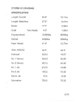
Page 107: ...cement Ballast Mast Height SA I AREAS Mainsail No 1 Genoa No 2 Genoa No 1 Jib Storm Jib Spinnaker 33 z 27 1 11 7u 5 6 113101bs 4210lbs 45 10 sqfl 233 0 444 0 362 0 251 0 90 0 1045 0 10 1 1 m 8 21m 3 5...

Page 108: ...cement Ballast Mast Height SAIL AREAS Mainsail No 1 Genoa No 2 Genoa No 1 Jib No 2 Jib Storm Jib Spinnaker 33 2 27 0 11 7 4 0 123551bs 4990lbs 41 9 sqft 200 0 333 0 267 0 212 0 165 0 70 0 756 0 1 0 11...

Page 109: ...l t ength Waterline Beam Dratt Fin Keel Twin Keels 34 7 27 6 1z 3 4 gu 4 5 151801bs 5707lbs sqft 242 0 349 0 100 0 866 0 10 54m 8 38m 3 74m 1 42m 1 34m 6900k9 2588k9 2400k9 14 91 m sqm 22 5 32 5 9 3 8...

Page 110: ...6171lbs 42 10 sqft 240 0 492 0 403 0 296 0 221 0 83 0 850 0 10 54m 8 38m 3 74m 1 50m 1 19m 5760k9 2600k9 2800k9 13 05m sqm 22 3 45 7 37 4 27 5 20 5 7 7 79 O Draft Fin Keel Twin Keels Displacement Ball...

Page 111: ...71lbs 42 10 sqft 240 0 485 0 398 0 28B O 204 0 82 0 11 35 0 10 54m 8 38m 3 74m 1 50m 1 19m 5708k9 2600k9 2B00kg 13 05m sqm 22 3 45 1 37 0 26 8 19 0 7 6 105 4 Draft Fin Keel Twin Keels Displacement Bal...

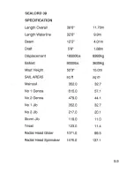
Page 112: ...REAS Mainsail No 1 Genoa No 2 Genoa No 1 Jib No 2 Jib Storm Jib Trisail Radial Head Glider Radial Head Spinnaker 35 8 30 5u 12 6u 4 11u 155001bs 6600lbs 52 ou sgfi 296 0 540 0 445 0 328 0 228 O 115 0...

Page 113: ...S Mainsail No 1 Genoa No 2 Genoa No 1 Jib No 2 Jib Storm Jib Trisail Radial Head Glider Radial Head Spinnaker 38 6 32 6 12 2 5 6u 185001bs 8000lbs 50 3u sgfi 352 0 615 0 479 0 352 0 217 0 119 0 123 0...

Page 114: ...AS Mainsail No 1 Genoa No 2 Genoa No 1 Jib No 2 Jib Storm Jib Trisail Radial Head Glider Radial Head Spinnaker 40 6 33 6u 1z 2 5 6u 185001bs 8000lbs 50 3 sgft 352 0 615 0 479 0 352 0 217 O 119 0 123 0...

Page 115: ...l Q llllf TE R EV YAGHTS F R E it 988 INTRODUCTION EQUIPMENT CHART 10...

Page 116: ...in the relevant section descriptions itemising current production yachts HULL Section SAILS AND RIGGING Section GAS SYSTEM SECIION ELECTRICAL SYSTEMS SECIION MAINTENANCE SectioN Systems and equipment...

Page 117: ...T LLLLkk E cggg_qgg_sEgggggg s FFFFFFFFFFFFFFFF c E c ooo t D l c YY o o o o o o o q q q q q o q q q o o OOOOa a o a a a a o oooo a 6 lit zit 6 6 6 6 6 6 a NNR t Y t t F E q A 5 g 5 H 9 3 g g s 8 F E...

Page 118: ...6 E E EE L L L L L L L L X X I g a t F P P F ggggggggPveclalE E tr tr i tr tr tr tr 5 5 F F 5 i F 5 5 5 5 5 5 c c c c c c c c csg ggpBeB e9 9es iDiDOaDoooooA ggggyy Y 1 cyY o o o o o o o o d d cL cl o...

Page 119: ...t t l 1 tEEHl WHITLOCK SYSTEMS Gobra and Mamba Systems Titan System Maintenance...

Page 120: ...ock steering systems were fitted to pre 1988 Westerly yachts The type depends on the year of manufacture and the availability of steering systems These systems were the Cobra Mamba and Titan Gobra and...

Page 121: ...m only are fully sealed and require no maintenance The bevei gears are lubricated with a specialthixotropic grease which will last many seasons without repacking any major voyage and clamp bolt tog st...

Page 122: ...ng lnternationaiYacht enamel For larger areas pri r to top coat use a two paft aluminiu etch primer Titan System This system uses two stainless steel wires running in condu it to a quadrant fitted to...

Page 123: ...ish of the pedestal with fresh watei Wax with conventional car polish 1 2 Ensure the stainless steel spiral pin is correctly fitted in the sprocket 1 3 Lubricate bushes using silicone based light grea...

Page 124: ...r damage and no feel 3 Quadrant 3 1At least twice a season and before any major voyage check security of quadrant bolts Lubricate eyebolts and sheave bush with silicone based light grease 3 2At the st...

Page 125: ...ENGINE SYSTEMS STERN GEAR Bukh System Bronze lnboard Gland Assemblies...

Page 126: ...INE SYSTEMS following addresses may helP STERN GEAR Various types of stern gear were fitted to older models Bukh System Reservoir Stern Tube Hexible Tube Rear Bearing Stuffing Box Ffg 1 Brrkh Slatem 1...

Page 127: ...ar oil 2 Every 3 seasons renew the 3 ring seals in the stuffing box A 3 Excessive oil consumption indicates defective ring seals Bronze lnboard Gland Assemblies Some early yachts are fitted with bronz...

Page 128: ...1 988 WATERA VAST SYSTEMS I AVAC MARINE TOILET Operating lnstructions Maintenance Winterisation Pump Valves Spare Parts I AVAC TOILET WITH HOLDING TANK Operation SL 4OO SERIES MARINE TOILET Operating...

Page 129: ...STEMS Some older yachts are fitted with the Brydon marine toilet but mainly the Lavac and SL 400 toilets are used LAVAC MARINE TOILET 1 lnlet Seacock 2 Pump 3 Air Bleed Valve 4 Outlet Seacock Fig 1 La...

Page 130: ...low strokes 7 Wait for a few seconds for the vacuum to clear 8 Raise lid I Operate the pump until the bowl is clear of water 10 Close inlet and outlet seacocks Maintenance Pump Blockage Bleed Hole Blo...

Page 131: ...After 2 3 years the pump valves may fur up from salt water action This sialing is e si removeh by fl xing the rubber and scraping gently lt is rdcommended that the pump is checked every 2years and de...

Page 132: ...HOLDIN6 TANK Fig 2 I AVAC Toilet with Holding Tank Operation Valve positions for operation of the system are detailed in Table 1 Valve Positions 13 4...

Page 133: ...olding tank to hull discharge 1 1 PrFp waste from holding tank to deck discharge Closed Closed 1 Closed 2 Closed Glosed Open Table 1 Valve Positions SL 4OO MARINE TOILET The SL 400 marine toilet has b...

Page 134: ...eously 3 Push handle away from bowl B and pump up and down This will empty the bowl 4 Close inlet and outlet seacocks Note Use only very absorbent toilet paper Spare Parts Spare parts and repair infor...

Page 135: ...ously 3 Push handle away from bowl B and pump up and down This will empty the bowl 4 Close inlet and outlet seacocks Note Use only very absorbent toilet paper Spare Parts Spare parts and repair inform...

Reviews: