3.4. Connector Pinout
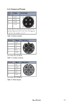
Pin
no.
Signal
Illustration
1
+DC1
2
1
3
4
2
+DC2
3
-COM
4
-COM
Viper supports redundant power connection. The
positive inputs are +DC1 and +DC2. The negative
input for both supplies is -COM
Table 3. Power connector
Pin no.
Signal
Illustration
1
NC
a
2
TX
3
RX
4
NC
a
5
GND
a
No Connect. Do not connect.
Table 4. Console connector
Pin no.
Signal
Illustration
1
DN
2
VBUS
3
NC
a
4
DC
5
GND
a
No Connect. Do not connect.
Table 5. USB connector
Viper-8 Series
11


