RT-610 HV/LV User Guide
Page 22 (31)
3.4 Connecting the Protective Earth
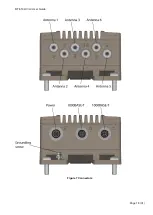
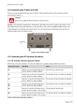
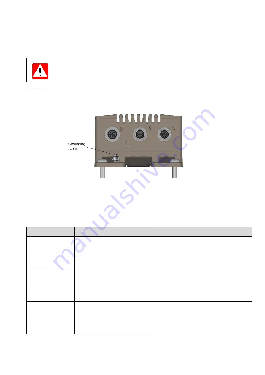
There is a single grounding connection point in RT-610. An M5 grounding screw at the housing is used for
grounding (see Figure 11).
Danger!
Do not use equipment without protective earth connection.
NOTICE: The grounding is organized by connecting the grounding to the ground contact in the casing. For the
grounding at the ground contact (M5 stud), a short wire with a cross section of
at least 6.0 mm
2
shall be used.
The grounding wire is set below the rip-lock washer. The nut is fixed for good reliable grounding contact. The
tightening torque of the nut shall be 2.0 Nm.
Figure 11 Grounding contact
3.5 Connecting the RF Antenna Interfaces
3.5.1 RF Antenna Interface Operation Modes
RT-610 has six antenna interfaces. The antenna interfaces are operating independently of each other.
Antenna Function
Operation
Notes
A1
Antenna 1 is used for both transmit and
receive of 802.11ac Wave 2 (5GHz)
The antenna A1 shall be used
A2
Antenna 2 is used for both transmit and
receive of 802.11ac Wave 2 (5GHz)
The antenna A2 can be enabled or disabled.
A3
Antenna 3 is used for both transmit and
receive of 802.11ac Wave 2 (5GHz)
The antenna A3 can be enabled or disabled.
A4
B3
Antenna 4 is used for both transmit and
receive of 802.11ac Wave 2 (5GHz)
The antenna A4 can be enabled or disabled.
B1
Antenna 5 is used for both transmit and
receive of 802.11ac Wave 1 (2.4 / 5GHz)
The antenna B1 shall be used
B2
Antenna 6 is used for both transmit and
receive of 802.11ac Wave 1 (2.4 / 5GHz)
The antenna B2 can be enabled or disabled.
Table 11 RF Antenna interface operation


