RT-610 HV/LV User Guide
Page 23 (31)
NOTICE: If antennas will be NOT used in customer application, the antenna connector MUST be terminated with
50 ohm termination.
NOTICE: The antenna interfaces are protected against lightning with special protection devices. To ensure correct
operation of these devices it is important, that the earth grounding contact is connected to protective earth as
described in chapter 3.4 with a short cable.
3.5.2 RF Antenna Connectors
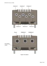
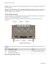
The Antenna connectors are identified with the text markings A1 (Antenna 1), A2 (Antenna 2), A3 (Antenna 3), A4
(Antenna 4), B1 (Antenna 5) and B2 (Antenna 6) in the mechanics.
The antennas might be fixed in antenna connectors directly or using antenna cables fixed to the antenna
connectors.
Figure 12 Antenna interfaces
NOTICE
: If one of the antennas is NOT used, the unused antenna connectors MUST be terminated with 50 ohm
termination.
Pin
Signal Name, Function
Notes
1
Center pin: RF signal
Connector Type: QMA
– Female
2
Connector body: RF ground
Table 12 Pinning: RF antenna connector


