background image

RT-610 HV/LV User Guide 

Page 25 (31) 


3.6.2 Ethernet Connector 

Connector Pin 

Signal name, Function 

Notes 

MX1 + 

Connector Type: Industrial ETHERNET M12-

Socket “X”-coded 

MX1 - 


MX2 + 


MX2 - 


MX4 + 


MX4 - 


MX3 - 


MX3 + 


Housing 

Ground 

For possible cable protection/ screening 

Table 14 Ethernet connector 

NOTICE: The pinning is compliant to IONA, Industrial Ethernet Planning and Installation Guide, Release 4.0. 

3.6.3 PoE Connection (X2 only) 

Connector Pin  1000 mode A 

1000 mode B  Notes 

1, 2 

DC+ 


Connector Type: Industrial ETHERNET M12-

Socket “X”-coded 

3, 4 

DC- 


5, 6 


DC- 


7, 8 


DC+ 


Housing 

Ground 

Ground 

For possible cable protection/ screening 

Table 15 PoE connection 

3.6.4 PoE Power Feed Specifications 

Parameter 

Value 

Notes 

Nominal Voltage 

48 VDC 


Voltage Range 

37 VDC 

… 57 VDC 


Power classification 

Class 3 


Table 16 PoE power feed specifications 


Summary of Contents for RT-610 HV

Page 1: ...REV A 6623 2290 2019 11 Westermo Network Technologies AB Sweden RT 610 HV LV User Guide ...

Page 2: ...RT 610 HV LV User Guide Page 2 31 ...

Page 3: ...ies including Free Libre Open Source Software FLOSS The specific license terms and copyright associated with the software are included in each software package respectively Please visit the product homepage for more information Upon request the applicable source code will be provided A nominal fee may be charged to cover shipping and media Please direct any source code request to your normal sales...

Page 4: ...tions 19 3 3 2 Temperature Alarms 19 3 3 3 Ambient Operating Temperature Range 19 3 3 4 Installations at Very High Temperatures 20 3 4 Connecting the Protective Earth 22 3 5 Connecting the RF Antenna Interfaces 22 3 5 1 RF Antenna Interface Operation Modes 22 3 5 2 RF Antenna Connectors 23 3 6 Connecting Ethernet Interface 24 3 6 1 Ethernet Port Features 24 3 6 2 Ethernet Connector 25 3 6 3 PoE Co...

Page 5: ...ctor 26 Figure 15 Ethernet Port for Factory Reset 28 Figure 16 Factory reset plug X coded 28 Table 1 Supported product versions variants and SW 9 Table 2 Important safety notes 9 Table 3 RT 610 xx delivery content 10 Table 4 Installation countries 10 Table 5 Output power limitations 12 Table 6 Product Identification Label 13 Table 7 Product label explanation 14 Table 8 Installation procedure 15 Ta...

Page 6: ...or income or any special incidental and consequential or indirect damages howsoever caused More information about Westermo can be found at www westermo com 1 2 References and related documents No Title 1 Software 6 Management Guide 2 RT 610 HV Datasheet 3 RT 610 LV Datasheet Further information about the product and relevant software tools can be downloaded from the product support pages at www we...

Page 7: ...RT 610 HV LV User Guide Page 7 31 SNMP Simple Network Management Protocol WebGUI Web Graphical User Interface WLAN Wireless Local Area Network ...

Page 8: ...N bands and configured as Access Point The Westermo configuration management tool WeConfig can be used for discovery and basic configuration and maintenance The configuration can be done via SNMP or via WebGUI The status information is available in local LED status indicators and through SNMP WebGUI Figure 1 RT 610 LV Picture The product functional block diagram is shown in Figure 2 Figure 2 RT 61...

Page 9: ...cessories such as damaged power cord Danger Never try to open the device There are no serviceable parts inside By trying to open the device you will be exposed to a risk of death or injury Warning Product warranty gets void and any liability will be disclaimed when opening the device Warning Read this user guide carefully before mounting installing and operating the device Warning Never unplug equ...

Page 10: ...imitations For detailed specification see Software 6 Management Guide 1 United States USA 2412 2472 MHz and 5180 5320 MHz 5500 5700 MHz 5725 5850 MHz Operation according to FCC limitations For detailed specification see Software 6 Management Guide 1 Canada CANADA 2412 2472 MHz and 5180 5320 MHz 5500 5700 MHz 5725 5850 MHz Operation according to IC limitations For detailed specification see Softwar...

Page 11: ...re is no guarantee that interference will not occur in a particular installation If this equipment does cause harmful interference to radio or television reception which can be determined by turning the equipment off and on the user is encouraged to try to correct the interference by one or more of the following measures Reorient or relocate the receiving antenna Increase the separation between th...

Page 12: ...ollowing output power limitations for ambient temperatures from 40 C to 70 C Active antennas Wave1 or Wave 2 Max output power with DC supply Max output power with PoE supply 1 25 dBm per chain 2 22 dBm per chain 3 20 dBm per chain 4 19 dBm per chain Table 5 Output power limitations ...

Page 13: ...pecification Value Notes Part Name RT 610 LV RT 610 HV Part Number 3623 073001 RT 610 LV EU 3623 073002 RT 610 LV NA 3623 073101 RT 610 HV EU 3623 073102 RT 610 HV NA Westermo part number SN XXXXXXXX Westermo internal serial number product code Manufacturing Date YYWW The date format is YY manufacturing year WW manufacturing week BAR CODE SN information Data matrix 104538 1 RR XXXXXXXX YYWW where ...

Page 14: ...ot be treated as household waste when disposing of it Instead it must be handled over to an applicable collection point for the recycling of electrical and electronic equipment By ensuring this product is disposed correctly you will help prevent potential negative consequences to the environment and human health which could be otherwise be caused by inappropriate disposal of this product Hot surfa...

Page 15: ...r installation See chapter 3 4 3 Antennas The antenna interfaces are installed based on customer requirements See chapter 3 5 4 Ethernet The Ethernet data interfaces are installed See chapter 3 6 5 Power Feed Power feed cable is connected the power may be already activated in the cable the power supply is switched on and verify that the LED indicators shows correct power up procedure See chapter 3...

Page 16: ...RT 610 HV LV User Guide Page 16 31 3 2 Dimensions for Fixing Points 3 2 1 Mechanical Overview Figure 6 Mechanical overview ...

Page 17: ...xing screw ISO 898 1 quality class 8 8 NOTICE All four specified fixing points must be used for fixing The fixing surface should be flat to have all fixing points connected to the surface The product has a membrane vent at the connector side of the product for equalizing pressure changes NOTICE The vent does not require any maintenance Any manipulations at the vent are not allowed Specification Va...

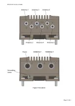
Page 18: ...RT 610 HV LV User Guide Page 18 31 Figure 7 Connectors ...

Page 19: ...ture Range This product includes a vent allowing controlled air exchange due to temperature changes Humidity is blocked by the vent To ensure correct operation over the whole specified temperature range certain aspects need to be considered The limits are defined for installations with free air flow in the installation environment It shall be noted that in real environment Limited air flow is risi...

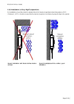
Page 20: ... the product is operated close to its maximum specified ambient temperature 55 C TAmbient 70 C it must be ensured that the natural convection is not blocked by objects close to the product Figure 8 Installation with blocked airflow shall be avoided Figure 9 Installation with free airflow good installation ...

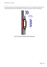
Page 21: ...he device at ambient temperatures above app 60C it is recommended to mount the device to a metallic base plate to improve the heat dissipation The base plate increases the surface to spread the heat Figure 10 Improved heat transfer based on fixing plate ...

Page 22: ...3 5 1 RF Antenna Interface Operation Modes RT 610 has six antenna interfaces The antenna interfaces are operating independently of each other Antenna Function Operation Notes A1 Antenna 1 is used for both transmit and receive of 802 11ac Wave 2 5GHz The antenna A1 shall be used A2 Antenna 2 is used for both transmit and receive of 802 11ac Wave 2 5GHz The antenna A2 can be enabled or disabled A3 A...

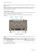
Page 23: ...with a short cable 3 5 2 RF Antenna Connectors The Antenna connectors are identified with the text markings A1 Antenna 1 A2 Antenna 2 A3 Antenna 3 A4 Antenna 4 B1 Antenna 5 and B2 Antenna 6 in the mechanics The antennas might be fixed in antenna connectors directly or using antenna cables fixed to the antenna connectors Figure 12 Antenna interfaces NOTICE If one of the antennas is NOT used the unu...

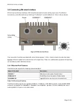
Page 24: ...es There is no additional line protection for lightning etc included at product hardware module 3 6 1 Ethernet Port Features The Ethernet port supports the following network standards Network Standard Description 10BASE T Ethernet over two pairs of twisted wires 100BASE TX Fast Ethernet over two pairs of twisted wires 1000BASE TX Gigabit Ethernet over four pairs of twisted wires Table 13 Ethernet ...

Page 25: ...g is compliant to IONA Industrial Ethernet Planning and Installation Guide Release 4 0 3 6 3 PoE Connection X2 only Connector Pin 1000 mode A 1000 mode B Notes 1 2 DC Connector Type Industrial ETHERNET M12 Socket X coded 3 4 DC 5 6 DC 7 8 DC Housing Ground Ground For possible cable protection screening Table 15 PoE connection 3 6 4 PoE Power Feed Specifications Parameter Value Notes Nominal Voltag...

Page 26: ... 4 3 2 starting from the coding mark Pin Signal Name Function Notes 1 VCC The positive supply voltage is applied 2 Not used 3 VCC The negative supply voltage is applied 4 Not used Table 17 Pinning PWR connector 3 7 2 Power Feed Specifications Parameter RT 610 LV RT 610 HV Notes Nominal Voltage 24 VDC 72 110 VDC Voltage Range 16 30 VDC 50 138 VDC Nominal current 0 6A 0 2A Guaranteed min max operati...

Page 27: ...RT 610 HV LV User Guide Page 27 31 3 7 3 Power supply ripple According to EN50155 the voltage ripple of the power supply may be 10 of the nominal voltage Otherwise too high touch current may result ...

Page 28: ...e Process for Factory Reset A factory reset is not typically needed for installation It is required if the device configuration is lost The factory reset functionality is included in both Ethernet port interfaces The factory reset process is performed using specific factory reset adapter Figure 15 Ethernet Port for Factory Reset 4 2 1 Factory Reset Adapter Specification The factory reset adapter i...

Page 29: ...nterfaces 2 Power the device 3 Wait until factory reset adapter is detected This is indicated by a YELLOW operation LED in combination with a RED status LED 4 Remove factory reset adapter within 15 seconds 5 A successful initiation of a factory Reset is indicated by a YELLOW BLINKING operation LED in combination with a RED BLINKING failure LED Table 19 Factory reset procedure After successful fact...

Page 30: ...ance shall be done by trained staff only 5 1 Cleaning Resistance to Chemicals In case the product is cleaned with cleaning chemicals the resistance to chemicals of the plastic parts needs to be respected The following plastic materials are used in the RT 610 Ethernet Connector Dust Cap Polyamide 66 PA66 Polyurethane PUR Pressure Equalizer Vent Polyamide 6 PA6 Polytetrafluoroethylene PTFE Stickers ...

Page 31: ... Description 1 Remove Cables Remove cables in the following order 1 Power cable or PoE cable 2 Antenna cables 3 Ethernet cables 4 Protective earth cable 2 Open Screw The four M6 screws in each corner of the RT 610 must be opened and removed completely 3 Exchange Lift the product out of its position Place a replacement unit to its position 4 Fix Screws The four M6 screws in each corner must be fixe...

Reviews: