Piezo-electl'ic C rystal Oscillato r
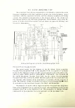
The crystal oscillator has one of two piezo-el L'ctric qu artz
crystals
having
the same frequency, connected in the grid circuit of the No. 2
·
1�-A
Oscillator
Vac u u m T ube designated as VIA. T h e other crystal remains i n readiness for
operation so that in the event of failure occurring in the first crysta l , the second
can be connected in the circuit by means of "C RYSTAL S ELECTOR" switch
D9A controlled from the front of the oscillator panel. Th ese
crystals
are
mounted in heat insulated cha mbers located on eith er side o f th e shielded
com
partment housing the oscillator circuit. Each chamber is capabl e
of being m
a
in
tained at a constant temperature
by means
of the temperatu re control eq u ip
ment provided. In parallel with the cr�'stal there is con n erkd t h e circuit
con
sisting of grid leak resistance R5A, filter resistance lHiA,
and µ:rid current
meter M2A. The direct current flowing- in the
gr
i
d circuit is indicated by
::Vlet
e
r
M2A marked "OSCI LLATOR GR I D CURRENT.''
The plate circuit of VlA receives its D C suppl�·
from
the 2,000-\·olt genera
tor through plate current meter l\f5A, plate feed resistances
rUl.
l A,
R�).2r\, and
R9 .3A, and inductance coil LlA. This \·oltag·e
is
re
duc
e
d
to the proper val ue by
series plate feed resistances R9.1A, R9.2A, and R9.:3A. The plate c: u rrent sup
plied to the crystal oscillator vacuum tube is ind i cated b�· m
e
t
e
r
:\I5A
mark
e
d
"OSCILLATOR PLATE CURRENT."
An untuned circuit is u sed as the output circ u i t of the crystal osc il lator.
Taps are provided on the output coil wh ich permit an adjustment to he made
for satisfactory operation of the crystal oscill ator. The radio frequency grid
voltage for the first amplifier is obtai ned d i rectly from the output coil by mean
s
of taps. Access to the plate and input taps qn the output coil is obta ined through
the panel window on the Oscillator Unit.
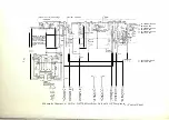
No.
D-87738
Oscillator Unit-
.
Top View of Oscilla tor Compartnient
[ 13 ]


