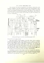
roup l i ng condensers are
t
o
n n
e
d
ed
i n c i rc u i t t h ro u g h
t h e a i d of
l i n k
s
. A. p p rnx i
mate tuning adj ustment
o f
L7B
i s
obta i n ed by 111<.'a n s o r
a
t
a p
w h i c h is p ro v i d l'd .
T h e final tu n i ng- i s accorn p l i slH '<l
l
'r
o
rn
th <::' fro n t o r t h e a 1 1 1 p l i f i <.1 l'
1 w n e l
l i.v
1 1 H.' a 1 1 ,::;
of th e lrnn d ,,·heel
marke<l " PO\\T E R
A M
P L !
F I E R T l T N I
NC . "
I � es01 w
rn·e
i s i n d i
cated by
a
minimum readi ng o
l
'
t h e pow er a m pl i l ier p l a t<.1 e u r re n t m e t <.' r
�1 � 1 : .
Th e c
a
p
ac
i
b
n
ce
ClOB
cou ples
t h <.' po w er a m pl i f i e r ou t p u t c i l 'c u i t t o t h
<.
1
antenna and is adj u sted i n
steps h
�
,
sPle<:t i o n o r su i t a b l e cou p l i n g: ca pac i t o rs .
The power a m p l i fier i s n
e
u
tr
a
l
i
z
e
d by con d<.' n se 1·
C� I IL
O n e
t
n m
i
n
a
l
o f t
h i
s
condenser is
perma n e n t l y c o n m'ded to t h e p l a t e t a p on eo i l Li l !
,
w h i l e t h e ot h e :
term i nal i s connecte<l to an
a<l
j
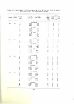
u st a b l e t a p w h i c h i s p l cleed ,
!'o r
a pa rt i e u l
e:
t r
operating- frequenc.v, on
t
h
e
prorer t u r n o l' co i l
U1 H
a s i n d i rn t ed i n
T
a
l
i
!
<
'
I V
on pag:e
-11 .
A.. 11tennu Circuit
The antenna c i rc u i t is t uned
a pp ro x i m a t e l y b.v
e:
t
d
.
i
u st i
n .!!.'
t he t e:1 p on
t h e
series a ntenna i
n
d
u
c
b
rn
ce
L�B
a n d t
h
e
f i n a l t u n i n g· i s done l'rom t h e
fr
o
n
t
u f
the ampl i fie1· panel b y a<l j u st i n g
t h e h a n d w h ee l
rn a rked " ..\. N T E X X ...\ T l ' l\
ING." Resonance i s i ndicated b
y
<1
ma x i m u m d 1:1 l l ect i on o r 111 ter
Yl
-
l U
m
a r ked
"ANTENNA CURRENT."
Radi o frequency ch oke coils
Li:3. I B
and
Ll:L�B
a re
connec t ed anoss t h e
cou pl i ng condenser for the p u rpose of allowing static c h a rges
o n
t h e
a n t
e
n n a
t o ftovv t o gTotmd.
The radio transmitter \\'as
p
ri
m
a
r i ly c!esi µ:ned to opera t e ,,· i th a
,l!,Tl rn � 1 cl
connection or a groun ded counterpoise, but
a n
i ns u la ted
c o u n t erpo i se 111a
.
\
'
he
used if necessary. A terminal for th i s connec t i on is provi ded a
t t h e
top
or
t he
transmitter and the req u ired chang·es are i nd icated i n t h e sc
h
e
m
at
i
c d i agTa m
of the No. 87739 Amplifier Unit ( see page
2:1 ) .
T h e ca pa c i t_,. o f the counter
poise to ground should not be less than
5 , 000
mi
c
ro
-
rn
i e
r
o fa r
ad
s i n onil'l' to
keep its voltage to ground below 1
,000.
Monitoring Rectifie ;o
A monitoring recti fier is provided to rectify a portion o r t h e a n tenna c u r
rent for monitoring purposes. Th is rectifier consists of a No.
2 0 5- I >
Vacuum
Tube designated V5B, w ith the grid and plate strapped tog-ether. The radio
frequency input voltage for the operation of this recti fier is obtained from t h e
tapped condenser
Cl
7B which is connected across the coupling condenser C l OB.
The variable taps on condenser
Cl
7B provide a convenient means for adj ust i n g
t h e input voltage t o the rectifier. T h e audio frequency component of the output
passes through transformer T2B to terminals 2 1 and 22 for connecti on to rnon
i
toring circuits. The direct current component of the output is fed th rough relay
S3B which closes contacts which may be u sed to operate local signal l igh t
circuits through terminals 25 and 26, thus affordi ng a v isual indication that t h e
transmitter is in operation.
[
35 ]


