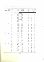
rnnvenient tabular form some suggestions for the adj ustment of the tuning
condenser C7B and coupling condenser C l OB, wh ich may be used in adj usting
the power a m p l i fier plate c urrent and the power amp l i fier output current to
w i th i n the ,·::d ues speci fied in Table V, page
44.
Some further consi derations of the adj ustment of t u n i ng condenser C7B
and coupl i ng condenser Cl OB follow and may prove helpful.
There a re two methods
of
i ncreas i ng: the power amp l i fier plate circuit
i m peda nce. One mdhod is to i ncrease the reactance of th e condenser branch of
the output c i rcuit, i.e. , decrease the val ue of the tuning condenser C7B ; the other
meth od is to loosen the coupli ng, i .e., i ncrease the capacity of the coup l i ng con
dt•n ser
C I O I L
Tlw two methods have the same effect on the power ampl i fier plate
e u rrtint ( a decrease) but the first method decreases the power amp l ifier output
cu rren t , wh ile the latter i n c reases it. For a decrease in power amplifier output
e i rc u i t im pedance the reverse holds true ; the tun i ng condenser C7B may be
increased or the cou pl ing condenser C l OB may be decreased in capacity. Either
o f th ese
1
\V O
adj ustments will increase the plate current. However, the power
ampli fier closed c i rcuit cu rrent is increased in the first adj ustment and decreased
in th e second adj ustment.
It will be found that large changes in e ither condenser C7B or ClOB may
req u ire
a
change in the taps on tuning inductance L 7B. ( Both taps are moved
togeth er. ) Th i s tap chang:e will amount to one or two turns and must be
obta i n ed
by
t rial. The data gi ven in Table
VIII
indicates the directions the tap
change w i l l take in order to bring the circ u i t again in tune.
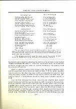
TADLE
V i l
1 -AD.J UST M ENT
O
F
POWER
A M PLIFIER TUNI NG INDUCTA NCE
CA l'AC ITY C HA NGE
(
la rge cha nges only )
TAP C H ANGE
I
n
c
r
ea
s
e
In
C7B
. . . . . . . . . . . . .
.
. . . .
.
. . . . . . . . . .
,
. . . . . . . . .
, ,
. . . .
Decreas(� turns
D
l•
c
re
a
s
e
In
C7B . . . . . .. . . . . . . . . . . . . . . . . . . . . . . . . . . . . . . . . . . . . . . . Increase turns
I n c rease
I
fl
C l OB . . . . . . . . . . . . . . . . . . . . . . . . . . . . . . . . . . . . . . . . . . . . Decrease turns
Dl•c n•ase
In
Cl OB . . . . .
.
. . .
.
. .
.
. . . . . . . . .
.
. . . . . . .
.
. . . . . . . . .
.
. . . Inc rease turns
In cases where one current ( Table V) is within the i ndicated range and
the other one is not, the procedure in Table VII should be followed as the first
operation. This will either bring both currents to proper values or will enable
Table
V I
to be used for the second adj ustment.
When the adj ustments are made in this manner it is desirable to keep a
record of current indications for the various capacities used. Thi s record may
take the following form :
Value of
Value of
Power Amplifier
Power Amplifier
Antenna
C 7 B
C l O B
Output Current
Plate Current
Power
The adj ustments giving currents nearest to the exact values of Table
V
may then be chosen. The closed circuit inductance
L7B
should be adjusted to
give a minimum power amplifier plate current, and the antenna inductance
L8B should be adj usted to give a maximum antenna current. The output of the
transmitter may now be adj usted to give the antenna current corresponding to
[ 46 ]


