background image

TCI Library  

www.telephonecollectors.info 

Summary of Contents for MAGICALL KS-19594

Page 1: ...r sons outside the Bell System without the written ap proval of the Central Region Engineering Manager SPECIFICATIONS Operating Ambient Temperature 20 to 120 F Power Consumption During Standby During...

Page 2: ...plete interchangeability of all component items dialer unit dial in unit cartridges and power supply with out requiring any readjustment The KS 19594 Ll dialer unit is the basic compon ent of this dia...

Page 3: ...4 Lldialerunit equippedwith a KS 19594 Ll2 cover a KS 19594 L2 dial in unit a KS 19594 L3 power supply and a subscriber instruction leaflet DASA No MIB A65 The KS 19594 L102 dialer assigned for conven...

Page 4: ...pressed This prevents it from turning when the tape drive motor is running 5 Plug Dial in Unit in rear of Dialer 6 Press CALL button Do not proceed until WAIT light goes out 7 Dial the number exactly...

Page 5: ...ialer Units Dial In Unit Power Supply Cartridge l Application W Eo Co 92554 W E Co 92555 W E Co 92556 W E Co 92557 This section outlines the methods and equip ment for repair of the KS 19594 MAGICALL...

Page 6: ...t loosen setscrew 32A Fig 9 on front clutch and adjust for 045 inchgapandlightly tighten setscrew making certain that the setscrew is properly oriented on the flat of the shaft With the CALL button de...

Page 7: ...ype CB or Equivalent b Fiber Washer per BTL drawing B 574349 DASA Corp c Pinion shaft per BTL drawing B 575159 DASA Corp DASA 2042 Gear per BTL drawing B 575163 DASA 2047 and Tinnerman nut C12044 012...

Page 8: ...d insulator Then replace the board and tighten the screws stamp the front right hand corner of the top circuit board per paragraph 2 1 to also indicate that this change was made Fig 4 One piece plasti...

Page 9: ...solder the 220 ohm resistor and new capacitor together Use spaghetti or shrinkable tubing where necessary to prevent short circuits Dress components against dialer frame 2 6 2 On dialers with serial...

Page 10: ...The remaining settings should be as shown in paragraph 2 1 Set the trigger slope switches to and Again play back the sequence of O s The COWlter should read between 57 7 and 64 5 milliseconds Set the...

Page 11: ...e Dial In Unit is returned from the field test it in conjunction with a known good list 1 Dialer Connect the telephone set cord to the spring terminals on the RS 16767 according to the color code Conn...

Page 12: ...nds after the Call Button has been released the Head Motor control timer will reset the Head Motor Control F F and stop the Head Motor 3 1 3 Dial rotated Off Normal closes 8403 Dial Shunt Contacts a M...

Page 13: ...n Unit pulse speed incorrect Cannot adjust Break time or Make time Head doesn t move Doesn t pulse out 0 6 second interdigital time incorrect Doesn1 t scan e Head Motor Control Timer stops Head Motor...

Page 14: ...Make time is adjusted as follows a If it is more than 40 msec re duce the gap between the open pulsing contacts b If it is less than 40 msec widen the gap between the open pulsing contacts 6 Motor Co...

Page 15: ...9 Dialer TCI Library www telephonecollectors info...

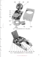
Page 16: ...D P401 COVER ASSEMBLY Fig 10 Disassembled Dial In Unit Parts Location R502 R501 M501 R504 CR501 C501 R503 5501 K501 CR502 M502 5502 Fig 11 Partially Disassembled Dialer Unit Chassis Parts Location 17...

Page 17: ...CR104 Cl05 CRHX CR107 Cl07 Cl03 QlO Cl02 Cll4 CR118 CR120 Qll3 Clll CR117 CR116 Ql09 Cl09 Cl06 Cll6 CR115 Cl08 CR112 CR114 Cll2 CRlll CR119 CllO QllO Ql08 CR105 Fig 13 Multi Board Assembly FSll Trans...

Page 18: ...Rll4 Rl36 Rl66 Rll3 Rl46 Rlll Rll2 Rl09 Rl08 Rl07 RllO Rl58 Rl57 Rll5 RI22 RI21 Rll6 R117 RI49 Rl30 Rl32 Rl6S RlS9 Rl31 Rl34 RI23 RISI RI69 Rl64 RISO Rl26 Rl28 Rl24 RI25 RI27 Rl47 Rl33 Rl61 Rl68 Rl29...

Page 19: ...0205 R211 R201 R206 R205 Q204 Q201 R204 Ii SiJ iiiiif A Q203 CR202 Q202 R202 R228 C201 R227 R20Q Fig 15 Amplifier Printed Circuit Board FS2 Parts Location R226 Q208 R214 R207 C203 TCI Library www tel...

Page 20: ...SOURCE VOLTAGE Fig 16 Amplifier Printed Circuit Board FS2 CircuiTrace Points through EZJ 21 TCI Library www telephonecollectors info...

Page 21: ...18V TEST PO NT 28V SOURCE VOLTAGE Fig 17 Multi Board Assembly FSll CircuiTrace Points a El ID I and through m 22 TCI Library www telephonecollectors info...

Page 22: ...18V SOURCE VOLTAGE Fig 18 Multi Board Assembly FSll CircuiTrace Points Erlthrough llE 23 TCI Library www telephonecollectors info...

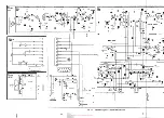
Page 23: ...I _ I I FLIP I I I I FLOP I I I I I I I L I I I I I I I I I I TO PULSING TIMER I I I I I I I I I I QlOl I I I Ql02 Qll3 I I I I SOURCE VOLTAGE I I TO DIALER UNIT I i AUX 1 to FEED I I I I FLIP BACK I...

Page 24: ...ircuiTrace point l l Q205 Collector W4 t 4VPP I CircuiTrace point fll Q208 Collector f 15VPP t W5 Circu iTrace point l Ql07 Collector f 15VPP l W6 Circu iTrace point fB QlOl Collector f 15VPP W7 Circu...

Page 25: ...WH 0 0 e K H l 0 c TO HEAD MOTOR CONTROL CIRCUIT J50 TERMINAL GUIDE ivv 04 5 o w_ _ s cE NI 1 I R210 5 6V I i SOURCE l I i I l PART OF fS2 l i i I I R22 1 ZIN I SOURCEI so i L J WH 26 Q207 QZ BLK WH...

Page 26: ...DE 27 PULSING TIMER QllZ 8 l V SCllEMATIC NOTES l All capacllor wlues art In mlcrolarad 2 All reslslo are ll4watt IOI unless otherwise speelfte I Resistors Rl52 Rl54 Risi an Rl57 selected In manufactu...

Page 27: ...51 Rl52 Rl53 Rl54 Rl55 R156 R157 Rl58 Rl59 Rl60 Rl61 R162 Rl63 Rl64 Rl65 Rl66 R167 Rl68 Rl69 Rl 70 R171 CRlOl CR102 CR103 CR104 CR105 CR105 CR107 CR108 CRllO CRlll CR112 CR113 CR114 CR115 CR116 CR117...

Page 28: ...10 1 4 Watt Carbon R224 39K 10 1 4 Watt Carbon R225 470K 10 1 4 Watt Carbon R226 lOK 10 1 4 Watt Carbon CONTROLS AND RESISTORS R227 7500 10 2 Watt Carbon R228 6800 10 1 4 Watt Carbon 2700n 10 1 4 Wat...

Page 29: ...national Rectifier J501 Jack Continental 9 20 SGD NOTES 1 Unless otherwise specified B nwnbers referred to are BTL drawing numbers Order fromDasaCorp as follows B part of KS 19594 Miscellaneous Parts...

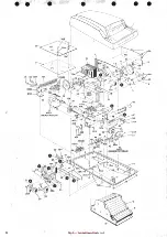
Page 30: ...ic Head 15 B 568872 Gear 16 B 568876 Gear 17 B 568843 Gear 44 B 568796 Carrier 44A Socket Hd Cap Screw 086 56x 3 16 2 Req d 18 B 568853 Reversing Link Ass y 18A B 573322 Washer 18B Retaining Ring B 56...

Reviews: