background image

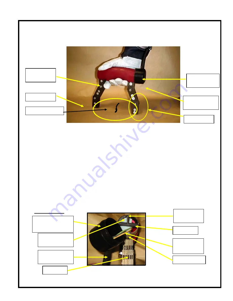
The WC-6X2 is a High Intensity AC Yoke, which induces a magnetic field into the 
ferrous material being tested.  The device should be used within the parameters set by 
the operational specifications within this guide. 

1. Solid State Push Button Switch – 

The Solid State Push Button

Switch was designed for comfort and safety.  While depressed, the switch delivers
power (AC) to the coil encapsulated in the Yoke housing.

 Output Module, where semiconductors are used to activate 

e magnetization field.

e must

t to twist or ‘pinch’ wires, on either the mounting bar or End Cap.

The Solid State Push Button Switch provides a ½ Watt control signal to the
electronic controls in the
th

itch on when plugging the Yoke into power. 

Do not hold the Push Button Sw

2. End Cap Rotation – 

The End Cap may be rotated to reposition the Cord

Protector (Strain Relief), for operator convenience, within the Bottom 120º  or Top
120º of the Junction tube.  Carefully remove the End Cap, followed by the internal
Cross Bar, and reposition the power wires.  Replace the cross bar, ensuring the
insulation disk (or tape) is in place and carefully reinstall the End Cap.  Car
be taken no

Bottom Exit 

Push Button 
    Switch 

Junction Tube 
   & End Cap 

Module (inside 
Junction Tube 

Pole Pieces 

Target Area 

Crack Orie

ntation 

Ground Lug 

  (Not used) 

Cross Bar 

  End Cap 

(Name 

Plate and  Fastener 

  not shown) 

Cord Protector/ 
   Strain Relief


   Module and 
Insulating Tape 

Junction Tube 

Power Wires 

White - Positive 
Black - Negative

Rear Leg 

WC-6X2 Operation Manual 

Summary of Contents for WC-6X2

Page 1: ...Operating Instructions WC 6X2 High Output Compact AC Yoke WC 6X2 Operation Manual 1 E s t a b l i s h e d 1 9 6 5 ...

Page 2: ...ctronic controls in the th itch on when plugging the Yoke into power Do not hold the Push Button Sw 2 End Cap Rotation The End Cap may be rotated to reposition the Cord Protector Strain Relief for operator convenience within the Bottom 120º or Top 120º of the Junction tube Carefully remove the End Cap followed by the internal Cross Bar and reposition the power wires Replace the cross bar ensuring ...

Page 3: ...ve to surface and near surface defects due to the Skin Effect as the field travels from one Pole Piece to another The WC 6X2 is designed to produce a very strong AC field to aid the operator while inspecting though nonmagnetic coatings or using extra scrutiny for inspecting critical components The Inspection Media Dry Powder or Wet Method Particles has a tendency to migrate toward interruptions or...

Page 4: ...he Pole Pieces farther apart If work piece configuration does not permit extending Pole Pieces reduce the contact area of the Pole Pieces on the work piece Follow the Operational Parameters outlined in these instructions 6 Maintenance After extended use the Yoke should be cleaned with a mild soap solution The unit should be visually inspected for any damage that could cause harm to the operator or...

Page 5: ...anty is void if the unit has been modified in any way or if it has been repaired by an unauthorized agency The end user agrees that any equipment s disposition when returned for warranty work is at the full discretion of Western Instruments as to whether a claim is under warranty or due to misuse Western Instruments warranty shall overlook normal wear however does not include operation outside the...

Page 6: ...overs Junction Tube Housing Hand Grip Protects Internal Coil Switch Cavity Hidden from View Name Plate Model Serial Number Volts Amps Frequency Cord Protector Strain Relief Power Cord AWG18 3 SOOW Rear Leg Assembly Pole Pieces Front Foot Upper Leg Front Leg Assembly Pole Pieces Upper Leg Rear Foot E s t a b l i s h e d 1 9 6 5 ...

Reviews: