background image

Lit. No. 49583, Rev. 02 

June 1, 2016

INSTALLATION INSTRUCTIONS

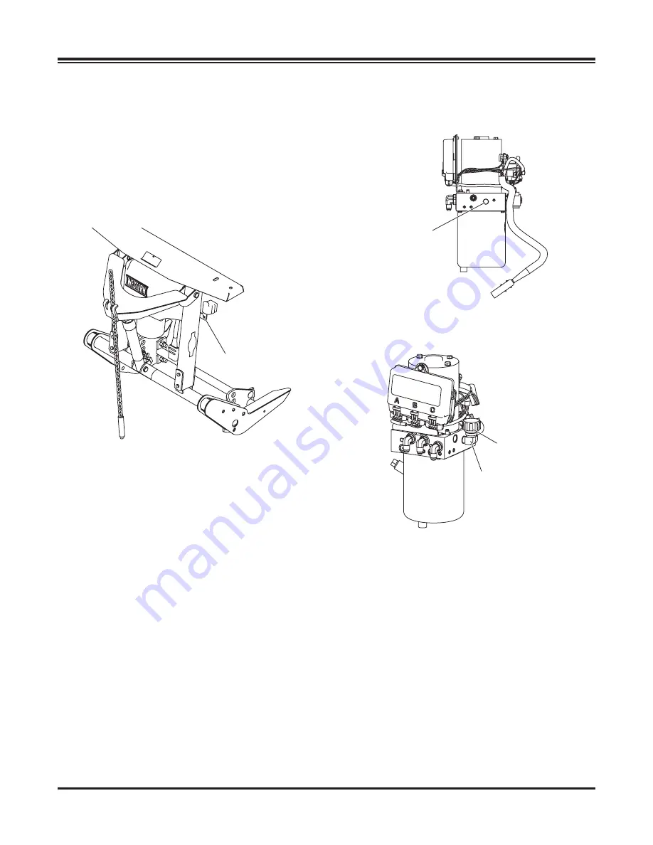
5.  Remove and discard the factory-installed pipe 

plug from the breather port.

6.  Install the 90° elbow into the port, pointing up. 

Install the breather into the elbow.

7.  Replace the hydraulic unit cover.

8.  Pivot the lift arm and lift ram up. Replace the two 

pins, washers, and hairpin cotters to reattach the 

lift arm to the lift frame.

9.  Move the driver-side lift chain back to the lift arm 

hook.

HYDRAULIC UNIT BREATHER 

INSTALLATION

1.  Position the lift frame in the upright position with 

the stands supporting the snowplow.

2.  Move the driver-side lift chain from the lift arm 

hook to the cable boot bracket on the side of the 

upper lift frame.

3.  Remove and retain the two hairpin cotters, 

washers and pins attaching the lift arm to the 

lift frame.

4.  Pivot the lift arm and lift ram forward and remove 

the hydraulic unit cover.

Breather

90° Elbow

Breather

Port

Move chain

to here

Summary of Contents for POLY PRO-PLOW Series 2

Page 1: ...PO Box 245038 Milwaukee WI 53224 9538 www westernplows com June 1 2016 Lit No 49583 Rev 02 A DIVISION OF DOUGLAS DYNAMICS LLC CAUTION Read this document before installing the snowplow CAUTION See your WESTERN outlet website for specific vehicle application recommendations before installation The Quick Match selection system has specific vehicle and snowplow requirements ...

Page 2: ...ot avoided could result in death or serious personal injury CAUTION Indicates a potentially hazardous situation that if not avoided may result in minor or moderate injury It may also be used to alert against unsafe practices Instruction Label Warning Caution Label WARNING CAUTION INSTRUCTION LABELS Become familiar with and inform users about the warning caution and instruction labels on the back o...

Page 3: ...ydraulic fluid under pressure can cause skin injection injury If you are injured by hydraulic fluid get medical attention immediately SAFETY PRECAUTIONS Improper installation and operation could cause personal injury and or equipment and property damage Read and understand labels and the Owner s Manual before installing operating or making adjustments WARNING Lower blade when vehicle is parked Tem...

Page 4: ...3 50 M36 x 4 00 2101 2701 1468 1952 325 M16 x 2 00 231 167 M18 x 2 50 318 222 Recommended Fastener Torque Chart Size Size Torque ft lb Grade 5 Grade 8 Metric Fasteners Class 8 8 and 10 9 These torque values apply to fasteners except those noted in the instructions Torque ft lb Grade 5 Grade 8 Size Size Torque ft lb Class 8 8 Class 10 9 Torque ft lb Class 8 8 Class 10 9 Inch Fasteners Grade 5 and G...

Page 5: ...s must be installed ballast must be installed if required and the vehicle must be parked on a level surface 1 Measure the distance d from the ground to the top edge of the receiver bracket Measure both sides and determine average value for d Top edge of receiver d 2 Use dimension d from Step 1 and the following chart to determine the proper pivot plate mounting position and pivot hole selection Pi...

Page 6: ... If the lift frame to A frame assembly needs to be in either of these configurations the pivot plates do not need to be repositioned Skip to Step 5 Configuration 3 or 4 If the lift frame to A frame assembly needs to be in configuration 3 or 4 the pivot plates must be removed and repositioned before the A frame is assembled to the lift frame 1 With the lift frame supported remove and retain the two...

Page 7: ...e height configuration chart and illustration Pivot Plate Configuration Chart Dimension D Configuration Stacking Stop 13 0 14 5 1 No 14 5 16 0 2 No 16 0 17 5 3 Yes 17 5 19 0 4 Yes 2 Insert a 1 4 roll pin 3 Do not cut the spring tie until after the final stand shoe adjustment WARNING The stand plunger spring is shipped compressed and tied Do not cut the spring tie until final stand shoe adjustment ...

Page 8: ...ft arm to the lift frame 9 Move the driver side lift chain back to the lift arm hook HYDRAULIC UNIT BREATHER INSTALLATION 1 Position the lift frame in the upright position with the stands supporting the snowplow 2 Move the driver side lift chain from the lift arm hook to the cable boot bracket on the side of the upper lift frame 3 Remove and retain the two hairpin cotters washers and pins attachin...

Page 9: ...Move the snowplow into normal operating position 4 Remove the protective packaging from the angle rams 5 Align the holes in the angle rams with the angle ram holes on the quadrant A and C Attach using the two 1 x 3 5 16 clevis pins from the top Secure with 1 4 x 2 cotter pins PRO PLOW Series 2 Blade MIDWEIGHT Blade A B C A B C 1 Locknut Pivot Bolt 1 x 3 5 16 Clevis Pin 1 x 3 5 16 Clevis Pin 1 4 x ...

Page 10: ...r bar with the end hole in the deflector and blade frame top angle Loosely install 5 16 x 1 1 4 cap screws and locknuts in the retainer bar holes Position the remaining retainer bars and loosely install the fasteners Tighten the fasteners starting from the center of the blade and working out toward each end BLADE GUIDE ASSEMBLY Insert the pointed end of the clamp into the coil of the blade guide r...

Page 11: ... Headlamp Swivel Grommet 1 2 Nut Cable Tie Anchor Headlamp Harness Headlamp Harness Cable Boot 2 Insert seven cable tie anchors into the 1 4 holes on the rear of the headlamp channel from inside the channel with the locking tabs horizontal 3 Install a split rubber grommet on each headlamp wire 3 from the headlamp and insert the grommet and wire into the slot on the rear of the channel 4 Route the ...

Page 12: ...ntrol ON and completely angle the blade to the left and right several times Raise and lower the snowplow several times Activate the control FLOAT function and manually collapse the lift ram all the way Turn the control OFF OPERATIONAL TESTS AND FINAL ADJUSTMENTS WARNING Keep 8 clear of the blade when it is being raised lowered or angled Do not stand between the vehicle and blade or directly in fro...

Page 13: ...ront of the blade If the blade hits or drops on you you could be seriously injured 3 Pivot the lift arm and lift ram forward and remove the hydraulic unit cover 4 Replace the two clevis pins washers and hairpin cotters to reattach the lift arm to the lift frame 5 Turn the quill IN clockwise to decrease drop speed Turn the quill OUT counterclockwise to increase drop speed 6 Stand 8 clear of the bla...

Page 14: ...imum transport height blade float and stacking stop clearance When the chain tension is correct the A frame will not contact the lift frame when the blade is fully raised 4 Check that the trip springs are adjusted correctly by confirming that the coils of the springs are separated slightly 5 Adjust the trip springs by loosening the bottom nuts and then tightening the top nuts until the coils of th...

Page 15: ...plug electrical systems plug covers shall be used whenever the snowplow is disconnected Vehicle Battery Cable is 12 volt unfused source VEHICLE LIGHTING CHECK 1 Verify the operation of all vehicle front lighting prior to connecting the snowplow harness 2 Check the operation of the snowplow lights with snowplow mounted to vehicle and all harnesses connected Turn signals and parking lamps Parking la...

Page 16: ...ommend optional equipment for snow removal Do not exceed vehicle ratings with a snowplow Western Products offers a limited warranty for all snowplows and accessories See separately printed page for this important information The following are registered or unregistered trademarks of Douglas Dynamics LLC FloStat MIDWEIGHT POLY PRO PLOW Series 2 PRO PLOW Series 2 UltraMount WESTERN Printed in U S A ...

Reviews: