16
Lit. No. 21857
June 15, 2003
Plow Headlamps
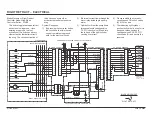
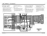
The headlamp circuit operates using
a high side drive system. High side
drive provides a hot 12V source to
activate the loads (coils, relays, etc.)
that share a common ground. The
headlamp switching circuit uses two
single pole double throw (SPDT)
relays. When combined with the
snowplow plug-in headlamp harness
and the vehicle harness, the relays
will automatically switch between
plow and vehicle headlamps as the
plow plugs are connected and
disconnected.
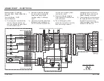
The vehicle harness has a brown
wire that is spliced into the vehicle
park lamp circuit. This wire feeds the
plow park lamps through the grill
connector and also powers the coils
of both relays. The other terminal of
the relay coils is connected to the
black/orange ground wire which also
goes to the grill connector. When
both the plow and battery cable plugs
are connected to the grill connectors,
a ground is completed for the relay
coil. When the vehicle park lamps
are turned on and the plugs are
connected, the relay coils will be
activated. This causes the relay
contacts to switch from the normally
closed contacts to the normally open
contacts. The normally closed
contacts power the vehicle
headlamps. The normally open
contacts power the plow headlamps.
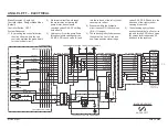
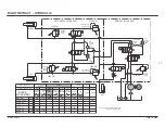
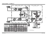
Refer to the Headlamp Test Diagram
in the Troubleshooting Guide.
It should be noted that:
•
The relay with the yellow,
orange and black wires
operates the low beam
headlamps.
•
The relay with the green, red
and white wires operates the
high beam headlamps.
•
The parking lamp circuit
provides power to both relays
at the same time.
•
Both plow plugs (12 pin and
battery cable) need to be
connected and the headlamp
switch must be on for the
relays to activate.
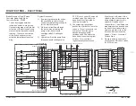
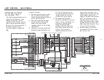
Daytime Running Lights
An additional fused pink wire is used
in place of the brown park circuit wire
to introduce power to the light relays.
The pink wire is connected to a circuit
controlled by the vehicle ignition
switch. When the vehicle ignition is
on and the grill connector plugs are
connected the relay coils will be
activated. This allows the DRLs to be
switched to the plow lights when the
vehicle headlamp switch is off. DRLs
use the same circuit as the regular
headlamps.
Testing High Side Drive Systems:
Connect the negative lead of the test
instrument (voltmeter) to ground and
positive lead to the positive side of
the load. A reading of 12 volts should
be indicated when the load is
activated; zero volts when load is not
activated.
THEORY OF OPERATION


