2
Westin Automotive Products, Inc.
320 W. Covina Blvd
San Dimas, Ca. 91773
Thank you for choosing Westin products
for additional installation assistance please call
Customer Service (800) 793-7846
www.westinautomotive.com
P.N.: 75-3085-RevB
ECO #: W16-0069
DATE: 10/7/16
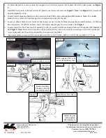
2. If vehicle has plastic covers, remove the designated covers where mounts will be placed from the rocker panel, see
Figure
1.
3. Install M8 u-clip nuts in the holes where the plastic covers were removed, see
Figure 2
.
Note:
See
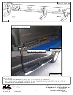
Figure 6
for placement
of all designated u-clips.
4. Loosely install mounting brackets to the previously install M8 u-clips with supplied M8 hardware.
Note:
The middle
bracket will be closer the front bracket then in comparison to the rear bracket.
5. Locate (1) plastic bracket cover (Item 14) and loosely secure it to the (6) brackets using the provided hardware: (2) M6 hex
head cap screws, (4) M6 flat washers, and (2) M6 nylon nuts. Repeat for every bracket. See
Figure
4.
6. Loosely install the Pro Traxx step bar assembly to the previously installed mounting brackets with supplied M10 hardware.
See
Figure 5.
Note:
Driver side step tube will be packaged in a clear poly tube and passenger side will be packaged
in a red poly tube, the Westin logo should face outward when installed.
7. Align and adjust as necessary then torque hardware: M8 to 15-18 ft-lbs., M10 to 30-35 ft-lbs., and M6 to 5-7 ft-lbs.
Install supplied M8 u-clip
nuts in designated areas.
Figure 2
Remove rubber covers.
Figure 1
Install mounting
brackets with sup-
plied M8 hardware.
Figure 3
Front Driver
Side Shown
Figure 4
Pro Traxx 4 Only
Install step bar
with supplied
M10 hardware.
Front Driver Side Shown
Figure 5


