TvPe
50-D H-50
Air Circuit
Brea b"'
3.0
2/J
LO
.8
. 6
.4
.2
I
I
·'
510 20
0
400
-Std.
Ott
--- Spcl. Low
Temp. Oil
/.
Hinimum Time Delay
2.
50% Ttme Delay
3.
Haximum
Time Delay
Temp.3o·c.
40
70
Current
Amperes
800
/400
Current
Per cent
/00
2000
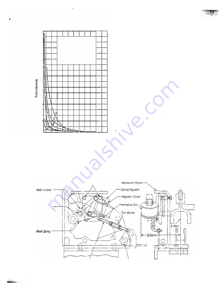
Fig. lQ-Calibration Curve for Inverse-time-limit Attachment
The oil in the dashpots should be renewed peri
odically. Fill with oil to % inch above the inside
bottom surface of the cylinder, with the plunger
removed.
Undervoltage Reset
Extension of Switch
Lrou
Undervoltaqe !1ountinq Screws
Adjusting Bolls
Undervolta�e Release
The undervoltag� release, Figure
11,
mounts
on the left hand s1de of the mechanism frame
with the two mounting screws as shown. The
undervoltage reset extension of the breaker lever
should operate between the undervoltage reset
spring and the undervol tage hold in lever. As the
mechanism closes, the reset extension of the breaker
lever strikes the undervoltage hold in lever, which
frees the undervoltage armature for operation in
case of voltage failure. As the mechanism opens.
the reset extension of the breaker lever strikes the
undervoltage reset spring, retrieving the armature
to its fully closed position. Failure to reset the
undervoltage armature completely will result in im
proper operation as the holding coil is not capable
of picking up the armature.
The turn buckle should clear the undervol tage
armature during the tripping movement. The turn
buckle should be set to secure Ys" clearance be
tween the end of the slot in the mechanism tripping
lever and the outside adjusting bolt head, with the
armature in the closed position .
The drop out voltage can be varied by regulating
the extension of the two undervoltage tripping
springs. A similar design, larger than shown by
Fig. 11, is used on later applications.
Cut-Off Switch
The 50-DH-50 Air Circuit Breaker has been sup
plied with two types of cut-off switches.
The cut-off switch supplied on the earlier models
is mounted on the left side of the mechanism just
back of the undervoltage attachment, Figure
12,
page
13.
It is a normally closed switch that is held
in the open position by means of an auxiliary
compression spring which acts on the auxiliary
switch lever. During the last portion of the closing
stroke the moving core strikes the switch pin which
ffechanism Trip Lever
Fig. 11-Undervoltage Operating Assembly
12
•
•
•
www
. ElectricalPartManuals
. com


