background image

Summary of Contents for 5026

Page 1: ...i CROSS COMPOUND STEAM DRIVEN AIR COMPRESSORS i INSTRUCTION PAMPHLET No 5026 JUNE 1940 SUPERSEDING ISSUE OF NOYEMBEl 1937 t COPYRIGHT 1940 BY THE WESTINGHOUSE AIR BRAKE COMPANY PIITSBURGH PA U S A om 1f ...

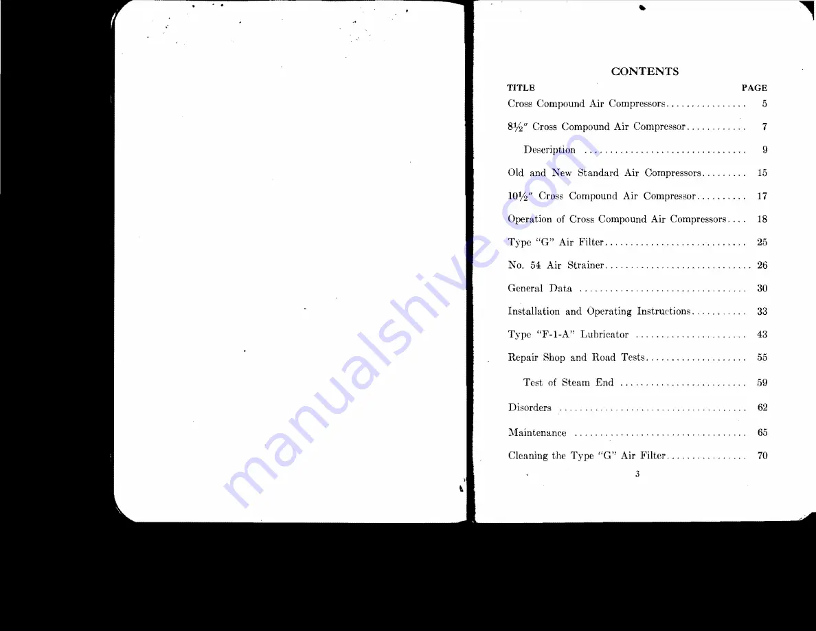
Page 2: ...rs 15 3 10112 Cross Compound Air Compressor 17 Operation of Cross Compound Air Compressors 18 Type G Air Filter 25 No 54 Air 26 General Data 30 Installation and Operating Instructions 33 Type F I A Lubrieator 43 Repair and Road Tests 55 Test of Steam End 59 Disorders 62 Maintenance 65 Cleaning the Type Gil Air Filter 70 ...

Page 3: ...n consequence longer trains of heavy large capacity cars The large brake cylinders and reservoirs required for the heavier cars the longer brake pipe due to the longer trains hauled and the greater num ber of flexible connections and fittings where leakage may occur combine to demand normally a larger volume of compressed air than ever before c The growing use of many pneumatically operated auxili...

Page 4: ...eam road service has a normal displacement of 150 cubic feet when operating on 200 pounds steam pressure The 8 120 was designed to operate on a lower steam pressure and has a normal displacement of 120 cubic feet when operating on 160 pounds steam pressure While the cross compound air compressor was orig inally designed to operate on saturated steam at a maximum of 200 pounds pressure the introduc...

Page 5: ...parts employed which comprise a the high pressure steam and low pressure air pistons connected by a Nickel Chrome steel piston rod drilled for the reversing valve rod which oper ates the reversing valve and which in turn actuates the main piHton valve controlling the admission of steam to and the exhaust from both the high and low pressure steam cylinders and b the low pressure steam and high pres...

Page 6: ...ed at a point where the oil will feed directly into the inlet pas sages to the high pressure air cylinder The center is tapped for inch pipe on both the front and back of the rear wall thus permitting of attaching the oil pipe at either the front or the back Our standard practice however is to connect the oil pipe at the front for the sake of accessibility with the back opening plugged Interchange...

Page 7: ...linder we have including the ends six separate chambers In this particular construction five of these chambers have permanent connections as follows The first chamber E behind the outer end of the first small piston to the atmosphere The second chamber A between the first and second pistons to passage a The third chamber F between the No 2 and No 3 intermediate pistons to the lower end of the low ...

Page 8: ...ich is slightly smaller see Fig 3 A port z through the piston valve equalizes the pressures at each end and the DESCRIPTION difference in size of the end pistons is such as to com pensate for the weight of the reversing valve and rod so that these parts are always in balance Chamber B between the two upper pistons is in communication with the exhaust port e Chamber K between the two lower pistons ...

Page 9: ...eloped for this particular service where ordinarily steam is not available at the high pressure used in railway braking service and the air pressures used are not so high The 10 compressor operates on the relatively Imy steam pressure of 100 pounds with a normal displace ment of 150 cubic feet of air at 80 pounds pressure The air cylinders are not water jacketed and no intercooler is required In a...

Page 10: ...ston admits steam through passage c to the upper end of the high pressure steam cylinder starting the high pressure steam piston 18 OPERA rTON HI on its downward stroke All parts have now assumed the position shown in Plate l A direct communication is now established where by live steam is supplied through passage a chamber A and passage c to the upper end of the high pressure steam cylinder downw...

Page 11: ...ive steam to chamber N and connecting passage tn cavity Band passage b thereby exhausting steam from chamber N on the faee of the large main valve piston Since the OPEHATION 21 pressure against the inner side of the large piston IS now greater than the pressure exerted against the inner side of the small piston 1 the piston valve moves to the or in the direction of chamber N and all parts are in t...

Page 12: ...ted its upward stroke the lower end of the low pressure air cylinder is filled with air at atmospheric pressure and the lower end of the high pressure steam cylinder is filled with live steam Here again the com pressor is reversed by means of the reversing valve plate attached to the high pressure steam piston coming in contact with the shoulder of the reversing valve rod which in turn actuates th...

Page 13: ... unit into the discharge opening Some of the heavier of dirt are carried downward and deJXlsited at the bottom of the casing cavity The cover is centrally threaded for the pipe connec tion to the air compressor and is also provided with two mounting lugs tapped for inch studs for mounting purposes The casing is of pressed steel and is attached to the cover by means of tie bolt 3 washer 12 and nut ...

Page 14: ...r studs Fig 10 Sectional View of the No 54 Air Strainer AIR STRAINER 27 In order to facilitate cleaning of the strainer be tween shoppings of the locomotive some roads use a blow back arrangement as illustrated in Fig 12 This consists of a pipe connected to the main rp prV l not to the discharge pipe in placed a cut out cock having a warning port from the outer end of the key into the cored passag...

Page 15: ...ed Cages and seats are cut from special grades of steel each piece made to exact dimensions and the threads seats etc individually checked to insure correct valve lift Air valves are forged from a special grade of steel bars and then oil tempered to produce a uniform structure They are individually checked for correct alignment of seat and wings The seats are spherically ground so that when valve ...

Page 16: ...20 compressor For higher boiler stearn pressures or where stearn and air conditions are such as to cause excessive speed of the compressor It is recommended that a choke fitting be installed in the stearn inlet connection The proper size choke will be speci fied upon application to our nearest district office Maximum allowable stearn pressures are 275 pounds for the former standard 81h 150 and 8 h...

Page 17: ...ed on the male threaded portion only and never in the socket Do not use red or white lead Figs 13 and 14 show the recommended arrangement and sizes of piping for one 8 compressor and also for a two 8V2 compressor installation The size of the steam supply pipe may be reduced one size when a choke fitting in the steam inlet is required to limit the com pressor speed as explained by notes under the i...

Page 18: ...then close the steam throttle valve 3 and open all the drain cocks on the 35 I iSTALLATION AND OPERATING INSTRUCTIONS compressor Keep the steam valve closed and the drain cocks open when the compressor is not working The main reservoir drain cocks should also be left open when the compressor is stopped for any length of time The compressor should always be stopped while the locomo tive is over the...

Page 19: ...hiS 1 necessary distribution to the Comoreasol S x I G Air Filter of the studs to either the COmpressor Or other substantial support so as to relieve the Intake Pipe of all unnecessary vibration and wear Use Independent D scharge Pipes of standard size and length and connect to Main Reservoir through a y Fitting and a short 2 inch extra strong pipe nipple 2 Pipe Air Discharge C Air Compressors Pip...

Page 20: ...ic lQ J 5 fj u N g air pressure is vented to the atmosphere thereby per L o 5 CXl c c mitting the filling operation to be performed while the o 0 0 0 compressor is running The stem portion 3 of the e o Ill 2 has a central passage b communicating at the bottom a eo U with the pipe connection leading to the air cylinder and 0 c e at the top with chamber a through the cavity in the U 5 cap nut This p...

Page 21: ...uniform quantities to the air cylinder of the compressor during each cycle of opera tion one filling of its oil chamber will supply sufficient lubrication to the compressor air cvlinder for the aver age trip of a locomotive A good grade of standard locomotive saturated steam valve oil only should be used in the air cylinders Super heater oil is not recommended for air cylinder lubrication because ...

Page 22: ...tor where reference numbers are given to identify the various as they will be explained The pipe connections are also numbered from 1 to 9 for convenience of refer ence and designation of each pipe as shown on the instal lation diagrams Reference 28 shows the ratchet wheel which is dowel ed to and readily removable from the oil pump actuating cam 27 Reference 33 shows the operating piston which op...

Page 23: ...trainers provided in the entrance to the oil chambers to prevent foreign matter from being carried in with the oil supply Ad ditional close mesh strainers 8 are provided around each individual oil pump intake as a further protectiop against sediment in the reservoirs entering the oil pumps One oil reservoir has one half the capacity of the other the small reservoir supplying two oil pumps for lubr...

Page 24: ...ttea as described later Operation Referring to section assembly Fig 17 as the low pressure air piston of the compressor moves up air pressure is developed on the face of the lubricator oper ating piston 33 and moves it against the force of piston spring 38 carrying with it pawl 4a which engages with a tooth in ratchet wheel 28 This rotates the ratchet wheel one notch and pawl 4 drops into a tooth ...

Page 25: ...livery pipe to the compressor or governor fitting and past the non return check in the terminal fitting to the part to be lubricated Each of the plungers makes one stroke durmg a revolution of the ratchet wheel which occurs during 00 double strokes of the compressor Adjustment The amount of oil delivered per stroke is controlled by the distance the plunger is allowed to move down ward the adjustme...

Page 26: ...Pres ure Air Cylinder 1 4 Heater Intake and Disehar e Pipes whi h ran be Re ereed if Desired Oil Delivered Per 100 Strokes 2 C C 2 C C 5 l 7 S 9 I Larp e Medium Small Large n 10 P Ys H Air Enginl Pipe to Low PressurE Ajr Cylinder Oil Delivery Line to High Pressure Steam Cylinder Oil Delivery Line to Reversin Valve i Oil Delivery Line to Air Piston of Governor Oil Delivery Line to Main Steam Line A...

Page 27: ...heir cor responding pipes are given in the table on page 51 When the method of installing these pipes has been determined it should be recorded in maintenance instruc tions so that there will be no chance for these pipes being improperly connected during repairs When the lubricator is applied to a compressor and before it is operated the delivery tubes must be filled with the proper oil This can b...

Page 28: ... Inspection and Testing of Steam Loco motives and Tenders dated 1919 snecified as follows regarding steam compressor tests The compressor or compressors shall be tested for capacity by orifice test as often as conditions may re but not less frequently than onre each three months The above Rules and Instructions also specify that with a 9 32 orifice to atmosphere and main reservoir pressure maintai...

Page 29: ...ain reservoir and its connections have been tested for leakage as above the compressor should be tested as follows The orifice disc is placed in a Apecial holder Fig 22 supplied for this purpose which should be connected to the main reservoir drain cock as illustrated in Fig 23 REPAIR SHOP AND HOAD TESTS with a test gage inserted between the disc holder and drain cock Then close the main reservoir...

Page 30: ...eam End u While the Interstate Commerce Commission makes no mention of tests of the steam end such tests should co be made to determine whether or not the efficiency of the c steam end of the compressor is lower than warrants con co e tinuing it in service or after having been repaired and II over hauled it is in proper condition to be returned to co service The test specifications given hereinaft...

Page 31: ... and the main reservoir pressure maintained at 53 pounds by bleeding it to the atmosphere at a given rate observations show that a speed of 100 single strokes per minute is attained with a boiler pressure of 122 pounds The curves show that if the steam end is in good average condition the 8 150 compressor operating against a main reservoir pressure of 53 pounds with 122 pounds boiler pressure shou...

Page 32: ...discharge valve causes heating destroys lubri cation and results in groaning 62 DISORDERS UNEVEN STROK jS OF THE COMPRESSOR air valves valves j 3 clogged valve passages j e strainers under upper intermediate valves 5 leaky air valves or 6 binding or cutting of the reversing rod Reml dy locate cause if possible and correct it by cleaning out clogged or dirty passages air valves and strainers replac...

Page 33: ...st excessive pressures inevitably results in high temperatures which tend to destroy the lubrication causing the air cylinders to cut and the groaning of the air compressor besides filling the discharge passage with deposits from burnt oil producing undesirable condensation of moisture in the brake system and in general reducing the overall efficiency of the compressor Under normal conditions the ...

Page 34: ...increases this lift more than 1 of an inch the seat is liable to be injured and the valve broken with consequent annoyance and delay For the purpose of readily determining the lift of air valves an Air Valve Lift Gage as illustrated in Figs 25 26 and 27 may be purchased from us To determine the lift of the upper air valve the gage is first applied to the top flange of the air cylinder as illustrat...

Page 35: ...ston first be entered in the cap nut Then pick up the cap nut and reversing valve assembly and insert CROSS COMPOUND A1H COMP U SSORS 69 assembly in the reversing valve bush observing that each piston with its rings properly enters the bush If the reversing valve assembly is inserted before applying the cap nut the reversing valve assembly should be lifted sufficiently to observe that the upper pi...

Page 36: ...rtieal position insert the blowing nozzle into the inner recess rn wing it up and down several times with a slight radial motion in order to insure uni form delivery of air to the complete inner surface of the unit In no event should units be blown from the outside inward before haye been thoroughly blown from the inside outward After the units huve been blown dryI they hould be plaeed in an own m...

Page 37: ...UL Endicott Building SAN FRANCISCO Matson Building SEATTLE Securities Building TOPEKA Columbian Building WASHINGTON D C Munsey Building ASSOCIATED COMPANIES WESTINGHOUSE BRAKE WESTINGHOUSE PACIfIC COAST BRAKE COMPANY SIGNAL COMPANY LTD Emeryville California Chippenham Wilts England CANADIAN WESTINGHOUSE BRAKE WESTINGHOUSE COMPANY LTD AUSTRALASIA Hamilton Ontario Canada PROPRIETARY LTD COMPAGNIA hA...

Page 38: ... PRESSURE STEAM CYLINDER Plate I 8 AIr Compn 88Ol DIagrammatic SectIon Downward Sttob of HJ h P rea8ure Steam low pressure air PIston 1 25 lWI 1 R Plate 2 8 AIr Compressor DIagrammatic Secti41 Stroke of High Pressure Steam low pressure al ...

Page 39: ...Type Beversinq Valve 25 fi AIR INLET Air Compressor Dia atic SectIon Downward Stroke Plate 2 8 a AIr Compresaor Dia tic Section Upward f HI h Pressure Steam low presaure air PIston Stroke of Blah Pressure Steam low presaure air Piston ...

Page 40: ...rd Tubing D X win thickn_ I 3 All Pipes to be cur ly clamped _ _ C C I i Lr ___ _ J lT I Supplementary View of Top Head of Compressor having Slide Valve I I t ype of Rever ing Valve I 1t 1 S Plate I TypicallnataUatlon Dlaanun of F I A Lubricator as applied to I One Standard 8 Cr088 Compound Air Compressor L _J ED I 1 Ieater Exhaust Pipe f O D Copper Tubing w I 1 J l 1 r r l J 1 i i Pipe Plug J j A...

Reviews: