TYP E CO CIRCUIT OP ENING R E LAY
OPERAT!OM I N D I CATOR "
AUX. CURRENT
TRANSF. SECOIIDARY
MOTE: TERM. 2 AMD 8 ARE TD 8E
.IUMPERED AT RELAY CASE
INTERNAL SCHEMAT IC
FRONT VIEW
DE-1011
-------------
COIITACTOR SWITCH
AUX. CURRENT
TRANSF. PRH4ARY
IIIDUCTlOII UNIT
CHASS I S OPERATED
SHORTI N G
SWITCII
URREIIT TEST .IAC•
TERMINAL
l83A055
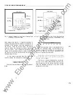
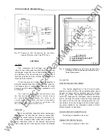
Fig. 1 . Internal Schematic of the Circuit Opening Type
CO Relay in Type FT2 1 Case.
ated clapper type devic e . A magnetic armature , to
which leaf-spring mounted c ontacts are attached, is
attracted to the magnetic core upon energization of
the switch.
When the switch closes, the moving
contacts bridge two stationary c ontacts completing
the trip circuit.
Also, during the operation , two
fingers on the armature deflect a spring located on
the front of the switch which allows the operation
indicator target to drop.
A core screw accessible from the top of the
switch provides the adjustable pickup range.
CHARAC T E R I STICS
The relays are available in the following c urrent
range :
2
AUX.
CUIIEIIT
TRAitSF .
SECOIIDARY
TEST
S lli i TCH
MOTE:
TERN.
2 AIID 8 AlE TO
IE
JUMPUED
AT IIU.Y
CAll
INTERNAL SCMEMATIC
DE-lOll
COIITACTOR
SIITCII
AUX. CURIEIIT
TRAIISF. PRIM.
IIIDICATI.IIG
IIISTA.IITUEOtiS
T R I P U II I T
I II
DU
C
T
IO
M
LUI
I
T
Clt.lJSIS OPEilAT£0
IKOITIMG SWITCH
CUIIfMT TEST .IACI
l83A054
*
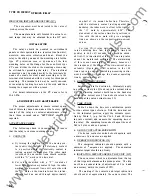
Fig. 2 . Internal Schematic of the Circuit Opening Type
CO Relay, With Indicating Instantaneous Trip,
in Type FT21 Case.
*
RANGE
4 - 12
4
5
TAPS
6
7
8
10
12
The circuit-opening relay i s recommended only
in the 4 to
12
ampere range. A lower range is not
desirabl e because the burden of a low-range trip
coil is too heavy on the current transformer. One
trip coil i s required for each relay.
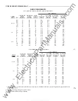
The burden on the current transformer at
-±
amp s.
i s 4.6
V A
with contacts
l l T
and
CO
cl osed and
5 . 7
V A
with contacts
open.
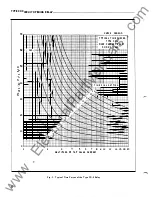
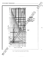
The time vs. current characteri sti c s are shown
in Figs. 3 to 9. These characteri stics give the con
tact clo sing time for the various time dial settings
when the indicated multipl es of tap value current
are applied to the rel ay.
www
. ElectricalPartManuals
. com


