background image

9

UL-ES-6CP30-WH 04

MOUNTING

MONTAJE

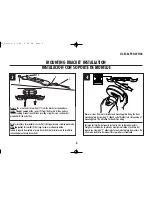
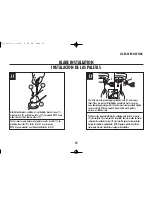
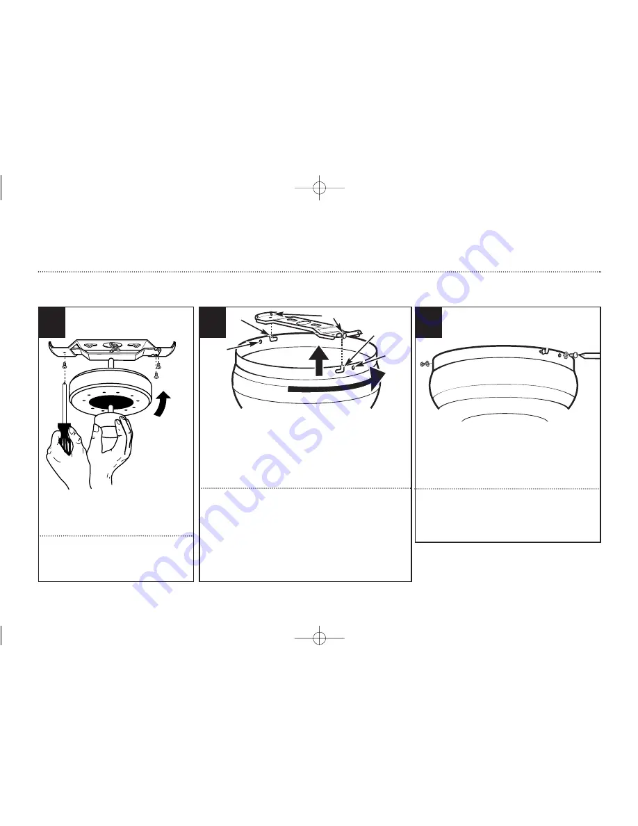
Push motor upward and attach the motor to

the mounting plate by tightly securing with

screws and washers provided.

Empuje el motor hacia arriba y fije el motor 

a la placa de montaje asegurando firmemente

con los tornillos y las arandelas incluidos.

8

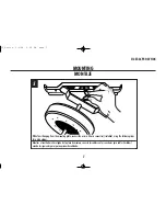
The decorative motor housing has two mating slots (1) and two

mating holes (2). Position both slots on the motor housing directly 

under and in line with two screws in the mounting bracket (3). 

Lift the motor housing, allowing the two screws to slide into the 

mating slots. Rotate the motor housing clockwise until both screws 

from the mounting bracket drop into the slot recesses. Tighten

screws securely. 

El alojamiento decorativo del motor tiene dos ranuras coincidentes 

(1) y dos orificios coincidentes (2). Coloque ambas ranuras del 

alojamiento del motor directamente abajo y en línea con los dos 

tornillos del soporte de montaje (3). Eleve el alojamiento del 

motor, permitiendo que los dos tornillos se deslicen dentro de las 

ranuras. Gire el alojamiento del motor en sentido horario hasta 

que ambos tornillos del soporte de montaje caigan adentro de las 

ranuras. Apriete los tornillos asegurándolos. 

9

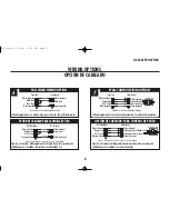
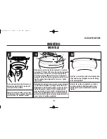
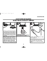
Install two screws and star washers into the mating holes
of the motor housing and tighten to secure the housing
to the mounting bracket.

Instale los dos tornillos y las arandelas en estrella en 

los orificios coincidentes del alojamiento del motor y 

ajústelos para asegurar el alojamiento al soporte de 

montaje.

10

1

2

3

1

2

UL_Petite  2/3/04  5:06 PM  Page 9

Summary of Contents for Contempra IV

Page 1: ...4 OWNER S MANUAL MANUAL DEL USUARIO MR N W 4 7 KGS G W 5 2 KGS PetiteTM Item Ítem No Finish Acabado 78107 Polished Brass Latón pulido 78108 White Blanco 78603 Antique Brass Latón antiguo UL_Petite 2 3 04 5 06 PM Page 1 ...

Page 2: ...ancing or during cleaning Do not insert foreign object between rotating blades 10 Attach the mounting bracket using only the hardware supplied with the outlet box Fan is only to be mounted to an outlet box marked Acceptable for Fan Support 11 To reduce the risk of fire or electric shock do not use this fan with any solid state fan speed control device or variable speed control 12 If this unit is t...

Page 3: ...sando sólo la tornillería suministrada con la caja de embutir El ventilador sólo se debe montar en una caja de embutir marcada Acceptable for Fan Support Aceptable para soportar ventiladores 11 Para reducir el riesgo de incendios o choques eléctricos no use este ventilador con un dispositivo de control de velocidad de estado sólido para ventilador o un control de velocidad variable 12 Si esta unid...

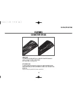
Page 4: ...es vary depending upon model ASPAS DE DOBLE CARA Las aspas del rotor de doble cara presentan dos superficies con un acabado de alta calidad Invirtiendo las aspas puede Ud producir un efecto decorativo adaptado a su ambiente o crear una decoración comple tamente nueva Observación las superficies de las aspas de doble cara son distintas en función del modelo FEATURES CARACTERÍSTICAS UL_Petite 2 3 04...

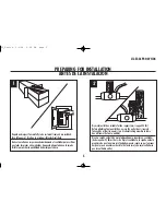
Page 5: ...EPARING FOR INSTALLATION ANTES DE LA INSTALACIÓN Quite el envoltorio e inspeccione detenidamente el ventilador para verificar que todas las piezas estén incluidas Apague la alimentación en la caja de fusibles para evitar la posibilidad de descarga eléctrica Use una caja de embutir de metal adecuada para soportar un ventilador debe soportar 35 libras Antes de fijar el ventilador a la caja de embuti...

Page 6: ...anura de la placa de montaje De este modo tendrá las dos manos libres para hacer el cableado 4 3 Remove the screws and star washers 1 from the bracket as shown above Loosen do not remove the screws 2 from the bracket as shown above Install mounting bracket to outlet box in ceiling using the screws and washers provided with the outlet box Quite los tornillos y las arandelas en estrella 1 del soport...

Page 7: ...wire connectors included using the following steps for wiring options Mientras el ventilador está colgado de la placa de montaje conecte los cables con los conectores para cables incluidos usando los siguientes pasos para opciones de cableado MOUNTING MONTAJE UL_Petite 2 3 04 5 06 PM Page 7 ...

Page 8: ...al tierra Blanco común Interruptor del ventilador vivo Interruptor de la luz vivo Verde de tierra Del Ventilador De La Casa conectar conectar conectar conectar Conecte el cable azul sólo si conecta un juego de luces al ventilador Control de pared Siga las instrucciones del diagrama anterior para hacer las conexiones de cableado para el ventilador con control de pared Blanco común Negro vivo Azul v...

Page 9: ...en screws securely El alojamiento decorativo del motor tiene dos ranuras coincidentes 1 y dos orificios coincidentes 2 Coloque ambas ranuras del alojamiento del motor directamente abajo y en línea con los dos tornillos del soporte de montaje 3 Eleve el alojamiento del motor permitiendo que los dos tornillos se deslicen dentro de las ranuras Gire el alojamiento del motor en sentido horario hasta qu...

Page 10: ...as Fije el conjunto de las paletas al motor usando las juntas reductoras de sonido del motor 2 y los tornillos para el motor incluidos Apriete los tornillos asegurándolos NOTA Algunos modelos no utilizan juntas para el motor arandelas o lengüetas de embalaje 12 11 Attach blade brackets to blades using the blade bracket screws 1 metal washers 2 and fabric washers 3 if provided NOTE Some models do n...

Page 11: ...itch housing to the white wire from the light kit with wire nuts provided Attach light kit to the switch housing using three small screws provided Identifique los dos cables en la tapa del alojamiento del interruptor rotulada FOR LIGHT para las luces Conecte el cable azul del alojamiento del interruptor al cable negro del artefacto luminoso y el cable blanco del alojamiento del interruptor al cabl...

Page 12: ...s are held by lightly pulling both chains in coupling Sujetar las cadenas largas de tiro con las piezas finales correspondientes a las cadenas del ventilador introduciendo el extremo de la cadena larga en la pieza de unión Asegúrese de que las cadenas están bien sujetas tirando ligeramente de ambas cadenas en la pieza de unión 16 UL_Petite 2 3 04 5 06 PM Page 12 ...

Page 13: ...13 UL ES 6CP30 WH 04 UL_Petite 2 3 04 5 06 PM Page 13 ...

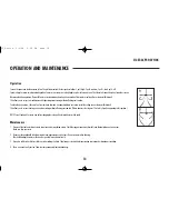
Page 14: ...This allows you to set your heating unit on a lower setting without affecting your comfort Please however refer to point 14 in Safety Tips when operating in this position NOTE Turn off and wait for fan to stop before changing the setting of the forward reverse slide switch Maintenance 1 Because of the fan s natural movement some connections may become loose Check the support connections brackets a...

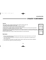
Page 15: ...ica la ilustración B Esto le permite ajustar la calefacción a un nivel más bajo sin que afecte su comodidad De todos modos por favor consulte el punto 14 de las Sugerencias de seguri dad cuando utilice el ventilador en esta posición NOTA Apague el ventilador y espere a que se detenga antes de cambiar la dirección de adelante atrás con el conmutador de tipo deslizante Mantenimiento 1 El movimiento ...

Page 16: ...peed controls DO NOT USE a Solid State variable speed control 5 Allow break in period of 24 hours Most noises associated with a new fan will disappear after this period All blades are weighed and grouped by weight Natural woods vary in density which could cause the fan to wobble even though all blades are weight matched The following procedures should eliminate most of the wobble Check for wobble ...

Page 17: ...e de estado sólido 5 Permita el rodaje del ventilador durante un período de 24 horas La mayoría de los ruidos asociados con el ventilador nuevo desaparecerán después de este período Todas las paletas se pesan y agrupan según el peso Las maderas naturales varían en densidad y podrían hacer que el ventilador oscile aún cuando todas las paletas estén agrupadas por peso Los siguientes procedimientos d...

Page 18: ...18 UL ES 6CP30 WH 04 UL_Petite 2 3 04 5 06 PM Page 18 ...

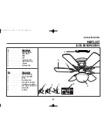
Page 19: ...Fan Speed Switch 6 Light Control Switch 7 Capacitor 8 Hardware Pack No Descripción 1 Soporte de montaje 2 Soporte para paleta 3 Paleta 4 Pantalla de vidrio 5 Interruptor de control de velocidad para ventilador 6 Interruptor de control de luz 7 Condensador 8 Tornillería 1 8 7 5 6 3 4 2 UL_Petite 2 3 04 5 06 PM Page 19 ...

Page 20: ...stinghouse Electric Corporation Made in China 2003 Westinghouse Lighting Corporation Westinghouse Lighting Corporation 12401 McNulty Road Philadelphia PA 19154 U S A Westinghouse Lighting Corporation titular de la licencia de Westinghouse Electric Corporation es una marca registrada de Westinghouse Electric Corporation Fabricado en China 2003 Westinghouse Lighting Corporation UL_Petite 2 3 04 5 06...

Reviews: