, �
Ol
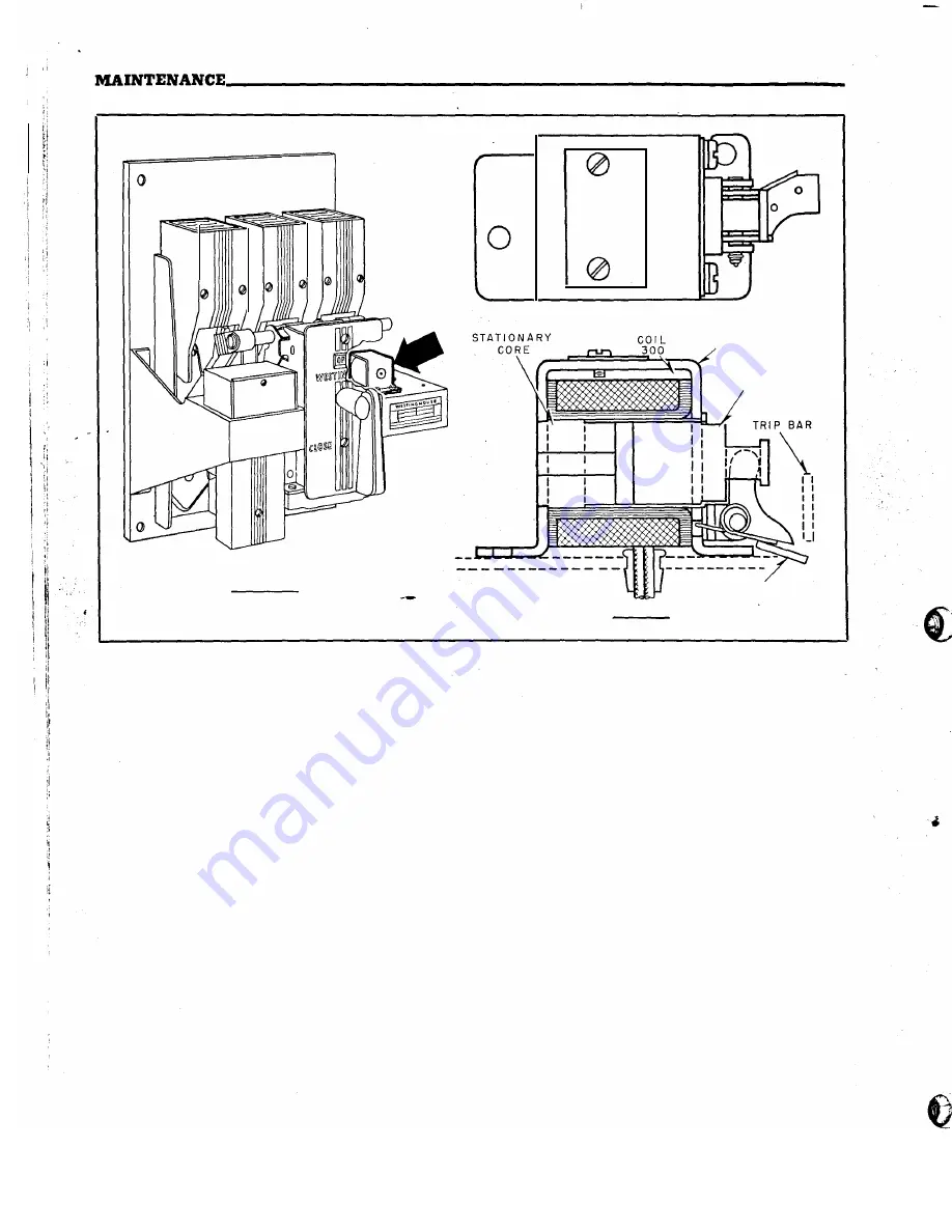
LOCAT ION
D ETA I LS
FR A M E
M O V I N G
C O R E
T R I P L E V E R
FIG. 10. Shunt Trip Attachment-Location and Construction Details
new overcurrents. Tighten all bolts after mounting
the overcurrent device.
CONTROL RELAY
The control relay mounts directly under the aux
iliary switch (see Fig.
9).
It is a single-coil, mechan
ically-tripped
device with the coil suitable for
con
tinuous energization. The operation sequence is
outlined
in
Fig.
8,
page 22. The contacts should
normally last the life of the breaker, but are replace
able
if
found necessary.
Check for correct adjustment by energizing the
relay coil with the breaker in the closed position.
If
the relay contacts touch momentarily, and draw
an arc, bend the release arm upward with a pair
of pliers. After bending, make sure the vertical
portion of the release arm does not rub either the
relay mold or the solenoid frame.
SHUNT TRIP ATTACHMENT
The shunt trip mounts on top of the platform
immediately to the right of the operating mecha
nism. (See Fig. 1
0).
- 24
It is non-adjustable and
is
intended for intermit
tent duty only. The shunt trip circuit must always
be opened by an auxiliary switch contact. Tripping
currents are tabulated in Table No. 2, page 12.
Inspection.
With the breaker in the open po
sition, manually push the moving core against the
stationary core and rotate the breaker handle to the
closed position. The breaker should be trip free.
The trip lever of the shunt trip should have ap
proximately a 1/is:inch clearance to the trip bar.
Maintenance.
Check for loose bolts and faulty
coils.
UNDERVOLTAGE TRIP ATTACHMENT
The undervoltage trip mounts on top of the plat
form, to the right of the shunt trip. (See Fig. 11).
Its function is to trip the breaker when the voltage
falls to between
30
to
60
percent of normal. Turn
the reset lever screw to secure approximately 14
oz. push out force on the moving core when the
latch releases.
The moving core is normally held magnetically
against the stationary core to hold the Micarta rod
(
www
. ElectricalPartManuals
. com
Summary of Contents for De-ion DB-15
Page 24: ...w w w E l e c t r i c a l P a r t M a n u a l s c o m ...
Page 27: ...w w w E l e c t r i c a l P a r t M a n u a l s c o m ...
Page 29: ...w w w E l e c t r i c a l P a r t M a n u a l s c o m ...
Page 31: ...w w w E l e c t r i c a l P a r t M a n u a l s c o m ...
Page 33: ...w w w E l e c t r i c a l P a r t M a n u a l s c o m ...
Page 35: ...w w w E l e c t r i c a l P a r t M a n u a l s c o m ...
Page 37: ...w w w E l e c t r i c a l P a r t M a n u a l s c o m ...
Page 39: ...w w w E l e c t r i c a l P a r t M a n u a l s c o m ...
Page 41: ...w w w E l e c t r i c a l P a r t M a n u a l s c o m ...
Page 43: ... w w w E l e c t r i c a l P a r t M a n u a l s c o m ...


