background image

2

ETL-ES-Carolina-R-WH14

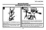
1.  Installation work and electrical wiring must be done by qualified person(s) in accordance with all applicable codes and standards (ANSI/NFPA 70), including fire-rated construction.

2.  Use this unit only in the manner intended by the manufacturer.  If you have  any  questions contact the manufacturer.

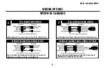
3.  After making the wire connections, gently push connections into outlet box with wire nuts pointing up. The wires should be spread apart with the grounded conductor and the equipment-grounding con 

         ductor on  one side of the outlet box and ungrounded conductor on the other side of the outlet box.

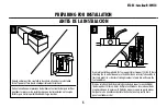
4.  Before you begin installing the fan, switch power off at service panel and lock service disconnecting means to prevent power from being switched on accidentally.  When the service disconnecting means 

         cannot be locked, securely fasten a prominent warning device, such  as a tag, to the service panel.

5.  Be cautious! Read all instructions and safety information before installing your new fan. Review the accompanying assembly diagrams.

6.  When cutting or drilling into wall or ceiling, do not damage electrical wiring and other hidden utilities.

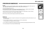
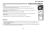
7.  Make sure the installation site you choose allows the fan blades to rotate without any obstructions. Allow a minimum clearance of 7 feet from the floor to the trailing edge of the blade.

8.  To reduce the risk of fire, electric shock, or personal injury, this fan must be mounted to an outlet box marked suitable for fan support, and use the mounting screws provided with the outlet box. (Mounting 

          must  support at least 35 lbs.)

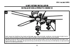
9.  WARNING! Do not bend blade holders during installation to motor, balancing or during cleaning. Do not insert foreign object between rotating blades.

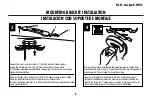
10.  Attach the mounting bracket using only the hardware supplied with the outlet box. Fan is only to be mounted to an outlet box marked “Acceptable for Fan Support”. 

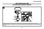
11.  WARNING! To reduce the risk of fire or electric shock, do not use this fan with any solid state fan speed control device, or variable speed control.

12.  If this unit is to be installed over a tub or shower, it must be marked as appropriate for the application.

13.  NEVER place a switch where it can be reached from a tub or shower.

14.  The combustion airflow needed for safe operation of fuel-burning equipment may be affected by this unit’s operation. Follow the heating equipment manufacturer’s guideline safety standards such as 

         those  published by the National Fire Protection Association (NFPA),  and the American Society for Heating, Refrigeration and Air Conditioning Engineers (ASHRAE) and the local code authorities.

15.  Before servicing or cleaning unit, switch power off at service panel and lock service disconnecting means to prevent power from being switched on accidentally.  When the service disconnecting means can

          not be locked, securely fasten a prominent warning device, such  as a tag, to the service panel.

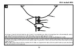
16.  All set screws must be checked and re-tightened where necessary before installation.

17.    The appliance is not intended for use by young children or infirmed persons without supervision. Young children should be supervised to ensure that they do not play with the appliance.

TOOLS REQuiREd

Phillips Screwdriver         Wire Cutters         Pliers        Step Ladder

Safety tipS

OBSeRVe tHe fOLLOWiNG: ReaD aND SaVe tHeSe iNStRUCtiONS

 WaRNiNG: tO ReDUCe tHe RiSK Of fiRe, eLeCtRiC SHOCK, OR peRSONaL iNJURy, MOUNt tO OUtLet BOX MaRKeD 'aCCeptaBLe fOR faN SUppORt Of 15.9 KG (35 LBS) OR LeSS' aND

 USe MOUNtiNG SCReWS pROViDeD WitH tHe OUtLet BOX aND/OR SUppORt DiReCtLy fROM BUiLDiNG StRUCtURe. MOSt OUtLet BOXeS COMMONLy USeD fOR tHe SUppORt Of

.LUMiNaRieS aRe NOt aCCeptaBLe fOR faN SUppORt aND May NeeD tO Be RepLaCeD. CONSULt a QUaLifieD eLeCtRiCiaN if iN DOUBt

Summary of Contents for ETL-ES-Carolina-R-WH14

Page 1: ...17 05 LBS Peso Neto 7 75 KGS ETL ES Carolina R WH14 Owner s Manual Manual del usuario Carolina Please write model number here for future reference Por favor incluya el número del modelo aquí para futura referencia ...

Page 2: ...ketusingonlythehardwaresuppliedwiththeoutletbox Fanisonlytobemountedtoanoutletboxmarked AcceptableforFanSupport 11 WARNING Toreducetheriskoffireorelectricshock donotusethisfanwithanysolidstatefanspeedcontroldevice orvariablespeedcontrol 12 Ifthisunitistobeinstalledoveratuborshower itmustbemarkedasappropriatefortheapplication 13 NEVERplaceaswitchwhereitcanbereachedfromatuborshower 14 Thecombustiona...

Page 3: ...asuministradaconlacajadeembutir Elventiladorsólosedebemontarenunacajadeembutirmarcada AcceptableforFanSupport Aceptableparasoportarventiladores 11 ADVERTENCIA Parareducirelriesgodeincendiosochoqueseléctricos nouseesteventiladorconundispositivodecontroldevelocidaddeestadosólidoparaventilador ouncontroldevelocidadvariable 12 Siestaunidadseinstalarásobreunabañeraounaducha debeestaridentificadacomoade...

Page 4: ...Combo Blade finishes vary depending upon model ASPAS DE DOBLE CARA Las aspas del rotor de doble cara presentan dos superficies con un acabado de alta calidad Invirtiendo las aspas puede Ud producir un efecto decorativo adaptado a su ambiente o crear una decoración completamente nueva Observación las superficies de las aspas de doble cara son distintas dependiendo del modelo Features Característica...

Page 5: ... fan to wobble pREPARING for installation Antes de la instalación Quite el envoltorio e inspeccione detenidamente el ventilador para verificar que todas las piezas estén incluidas Apague la alimentación en la caja de fusibles para evitar la posibilidad de descarga eléctrica Use una caja de embutir de metal adecuada para soportar un ventilador debe soportar 35 libras Antes de fijar el ventilador a ...

Page 6: ...forma de T adentro de la ranura de la placa de montaje De este modo tendrá las dos manos libres para hacer el cableado 4 3 Remove the screws and star washers 1 from the bracket as shown above Loosen do not remove the screws 2 from the bracket as shown above Install mounting bracket to outlet box in ceiling using the screws and washers pro vided with the outlet box Quite los tornillos y las arandel...

Page 7: ...ect the wires with wire connectors included using the following steps for wiring options Mientras el ventilador está colgado de la placa de montaje conecte los cables con los conectores para cables incluidos usando los siguientes pasos para opciones de cableado MOUNTING MONTAJE ...

Page 8: ...fan pull chain control PULL CHAIN WIRING OPTION WALL CONTROL WIRING OPTION Siga las instrucciones del diagrama anterior para hacer las conexiones de cableado para el ventilador con control de pared Siga las instrucciones del diagrama anterior para hacer las conexiones de cableado para el ventilador controlado con cadenilla de tiro OPCIÓN DE CABLEADO PARA CADENILLA DE TIRO OPCIÓN DE CABLEADO PARA C...

Page 9: ...lot recesses Tighten screws securely El alojamiento decorativo del motor tiene dos ranuras coinciden tes 1 y dos agujeros coincidentes 2 Coloque ambas ranuras del alojamiento del motor directamente abajo y en línea con los dos tornillos del soporte de montaje 3 Eleve el alojamiento del motor permitiendo que los dos tornillos se deslicen dentro de las ranuras Gire el alojamiento del motor en sentid...

Page 10: ... motor 1 y descártelas Fije el conjunto de las paletas al motor usando las juntas reductoras de sonido del motor 2 y los tornillos para el motor incluidos Apriete los tornillos asegurándolos NOTA Algunos modelos no utilizan juntas para el motor arandelas o lengüetas de embalaje 12 11 Attach blade brackets to blades using the blade bracket screws 1 metal washers 2 and fabric washers 3 if provided N...

Page 11: ...he white wire from the light kit Attach light kit to the switch housing using three small screws provided Identifique los conectores para cables de salida del artefacto luminoso y del motor y deslícelos para unirlos Conecte el cable azul del alojamiento del interruptor al cable negro del artefacto luminoso y el cable blanco del alojamiento del interruptor al cable blanco del artefacto luminoso Con...

Page 12: ...m the bottom of the light kit Install the bulbs not included Desenrosque y quite el florón 1 la tapa decorativa 2 la tuerca 3 y la arandela de caucho metal 4 de la parte inferior del juego de luces Instale las bombillas de luz no incluidas Light fixture installation Instalación del artefacto luminoso 14 4 3 2 1 ...

Page 13: ...ull chain operates smoothly Instale la pantalla de vidrio 5 en el juego de luces y ajuste la arandela 4 y la tuerca 3 en la parte inferior de la pantalla Asegúrese de que la cadenilla de tiro del ventila dor de techo pasa por el agujero lateral de la parte inferior de la pantalla Coloque la tapa decorativa 2 sobre la parte inferior de la pantalla de vidrio y asegúrela ajustando el florón decorativ...

Page 14: ...g Confirm chains are held by lightly pulling both chains in coupling Sujeta las cadenillas largas de tiro con las piezas finales correspondientes a las cadenillas del ventilador introduciendo el extremo de la cadenilla larga en la pieza de unión Asegúrese de que las cadenillas están bien sujetas tirando ligeramente de ambas cadenillas en la pieza de unión ...

Page 15: ...ion An upward airflow moves warm air off the ceiling area as shown in illustration B This allows you to set your heating unit on a lower setting without affecting your comfort NOTE Turn off and wait for fan to stop before changing the setting of the forward reverse slide switch Maintenance 1 Because of the fan s natural movement some connections may become loose Check the support connections brack...

Page 16: ...l reloj Una corriente de aire ascendente aleja el aire caliente del área del ventilador de techo como lo indica la ilustración B Esto le permite ajustar la calefacción a un nivel más bajo sin que afecte su comodidad NOTA Apague el ventilador y espere a que se detenga antes de cambiar la dirección hacia adelante atrás con el interruptor deslizante Mantenimiento 1 El movimiento natural del ventilado...

Page 17: ...not over tightened 2 check to make sure the screws which attach the fan blade holder to the motor are tight 3 Some fan motors are sensitive to signals from Solid State variable speed controls DO NOT USe a Solid State variable speed control 4 Allow break in period of 24 hours Most noises associated with a new fan will disappear after this period 3 If fan wobbles All blades are weighed and grouped b...

Page 18: ... que todos los tornillos del alojamiento del motor estén ajustados no los apriete demasiado 2 Compruebe para asegurarse de que los tornillos que fijan el soporte de la paleta del ventilador al motor estén apretados 3 NO USE un control de velocidad variable de estado sólido 4 Permita el rodaje del ventilador durante un período de 24 horas La mayoría de los ruidos asociados con el ventilador nuevo d...

Page 19: ...ade Bracket 3 Blade 4 Glass 5 Fan Speed Switch 6 Light Control Switch 7 Capacitor 8 Hardware Pack No Descripción 1 Soporte de montaje 2 Soporte para aleta 3 Aleta 4 Pantalla de vidrio 5 Interruptor de control de velocidad para ventilador 6 Interruptor de control de luz 7 Condensador 8 Tornillería 4 2 3 ...

Page 20: ...54 1029 U S A www westinghouselighting com WESTINGHOUSE and INNOVATION YOU CAN BE SURE OF are trademarks of Westinghouse Electric Corporation Used under license by Westinghouse Lighting All rights reserved Made in China ETL ES Carolina R WH14 ...

Reviews: