background image

17

ETL-ES-Hadley-WH20

If you have difficulty operating your new ceiling fan, it may be the result of incorrect assembly, installation, or 

wiring. In some cases, these installation errors may be mistaken for defects. If you experience any faults, please 

check this Trouble Shooting Chart. If a problem cannot be remedied, please consult with your qualified electrician 

and do not attempt any electrical repairs yourself.

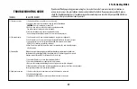
TROUBLESHOOTING GUIDE

TROUBLE 

1. If fan does not start:

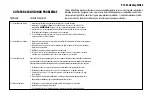
2. If fan sounds noisy: 

3. If fan wobbles:


4. If light does not work:

SUGGESTED REMEDY

1. Check main and branch circuit fuses or circuit breakers.

2. Check wire connections as performed in step #6 or #7 of installation. 


CAUTION:

 Make sure main power is turned off.

3. Make sure forward/reverse switch is firmly in up or down position. 

  Fan will not operate when switch is in the middle.

4. If the fan still will not start, contact a qualified electrician. 

  Do not attempt to troubleshoot internal electrical connections yourself.

1. Check to make sure all screws in motor housing are snug (not over tightened).

2. Check to make sure the screws which attach the fan blade holder to the motor are tight.

3. Some fan motors are sensitive to signals from Solid State variable speed controls. 

  DO NOT USE a Solid State variable speed control.

4. Allow “break-in” period of 24 hours. Most noises associated with a new fan will disappear 

  after this period.

All blades are weighed and grouped by weight. Natural woods vary in density which could cause 

the fan to wobble even though all blades are weight-matched. The following procedures should 

eliminate most of the wobble. Check for wobble after each step.

1. Check that all blades are screwed firmly into blade holders.

2. Check that all blade holders are tightened securely to motor.

3. Make sure that canopy and mounting bracket are tightened securely to ceiling joist.

4. If blade wobble is still noticeable, interchanging two adjacent (side by side) blades can redistribute 

the weight and possibly result in smoother operation.

1. Check to see that the wire connections in the switch housing are connected.

2. Check for faulty light bulbs.

3. If light kit will still not operate, contact a qualified electrician for assistance.

Summary of Contents for ETL-ES-Hadley-WH20

Page 1: ...Weight LBS Peso Neto KGS ETL ES Hadley WH20 OWNER S MANUAL MANUAL DEL USUARIO Hadley Please write model number here for future reference Por favor incluya el n mero del modelo aqu para futura referenc...

Page 2: ...usingonlythehardwaresuppliedwiththeoutletbox Fanisonlytobemountedtoanoutletboxmarked AcceptableforFanSupport 11 WARNING Toreducetheriskoffireorelectricshock donotusethisfanwithanysolidstatefanspeedcon...

Page 3: ...ministradaconlacajadeembutir Elventiladors losedebemontarenunacajadeembutirmarcada AcceptableforFanSupport Aceptableparasoportarventiladores 11 ADVERTENCIA Parareducirelriesgodeincendiosochoquesel ctr...

Page 4: ...bo Blade finishes vary depending upon model ALETA DE DOBLE CARA Las aleta del rotor de doble cara presentan dos superficies con un acabado de alta calidad Invirtiendo las aleta puede Ud producir un ef...

Page 5: ...n to wobble PREPARING FOR INSTALLATION ANTES DE LA INSTALACI N Quite el envoltorio e inspeccione detenidamente el ventilador para verificar que todas las piezas est n incluidas Apague la alimentaci n...

Page 6: ...del soporte con forma de T adentro de la ranura de la placa de montaje De este modo tendr las dos manos libres para hacer el cableado 4 3 Remove the screws 1 from the bracket as shown above Loosen do...

Page 7: ...the wires with wire connectors included using the following steps for wiring options Mientras el ventilador est colgado de la placa de montaje conecte los cables con los conectores para cables inclui...

Page 8: ...fan pull chain control PULL CHAIN WIRING OPTION WALL CONTROL WIRING OPTION Siga las instrucciones del diagrama anterior para hacer las conexiones de cableado para el ventilador con control de pared Si...

Page 9: ...recesses Tighten screws securely El alojamiento decorativo del motor tiene dos ranuras coinciden tes 1 y dos agujeros coincidentes 2 Coloque ambas ranuras del alojamiento del motor directamente abajo...

Page 10: ...1 y desc rtelas Fije el conjunto de las paletas al motor usando las juntas reductoras de sonido del motor 2 y los tornillos para el motor incluidos Apriete los tornillos asegur ndolos NOTA Algunos mod...

Page 11: ...g to the white wire from the light kit Attach light kit to the switch housing using three small screws provided Identifique los conectores para cables de salida del juego de luz y del motor y desl cel...

Page 12: ...from the bottom of the light kit Install the bulbs included Desenrosque y quite el flor n 1 la tapa decorativa 2 la tuerca 3 y la arandela de caucho metal 4 de la parte inferior del juego de luz Inst...

Page 13: ...ll chain operates smoothly Instale la pantalla de vidrio 5 en el juego de luz y ajuste la arandela 4 y la tuerca 3 en la parte inferior de la pantalla Aseg rese de que la cadenilla de tiro del ventila...

Page 14: ...onfirm chains are held by lightly pulling both chains in coupling Sujeta las cadenillas largas de tiro con las piezas finales correspondientes a las cadenillas del ventilador introduciendo el extremo...

Page 15: ...moves warm air off the ceiling area as shown in illustration B This allows you to set your heating unit on a lower setting without affecting your comfort NOTE Turn off and wait for fan to stop before...

Page 16: ...reloj Una corriente de aire ascendente aleja el aire caliente del rea del ventilador de techo como lo indica la ilustraci n B Esto le permite ajustar la calefacci n a un nivel m s bajo sin que afecte...

Page 17: ...to make sure all screws in motor housing are snug not over tightened 2 Check to make sure the screws which attach the fan blade holder to the motor are tight 3 Some fan motors are sensitive to signals...

Page 18: ...dos los tornillos del alojamiento del motor est n ajustados no los apriete demasiado 2 Compruebe para asegurarse de que los tornillos que fijan el soporte de la aleta del ventilador al motor est n apr...

Page 19: ...us GARANT A Este ventilador deWestinghouse Lighting se ofrece con una garant a limitada de por vida para el propietario original frente a defectos de material y de mano de obra Esta garant a sustituye...

Page 20: ...Blade Bracket 3 Blade 4 Glass 5 Fan Speed Switch 6 Light Control Switch 7 Capacitor 8 Hardware Pack No Descripci n 1 Soporte de montaje 2 Soporte para aleta 3 Aleta 4 Pantalla de vidrio 5 Interruptor...

Page 21: ...21 ETL ES Hadley WH20...

Page 22: ...22 ETL ES Hadley WH20...

Page 23: ...23 ETL ES Hadley WH20...

Page 24: ...154 1029 U S A www westinghouselighting com WESTINGHOUSE and INNOVATION YOU CAN BE SURE OF are trademarks of Westinghouse Electric Corporation Used under license by Westinghouse Lighting All rights re...

Reviews: