Westinghouse Type F-122 Oil Circuit-Breakers
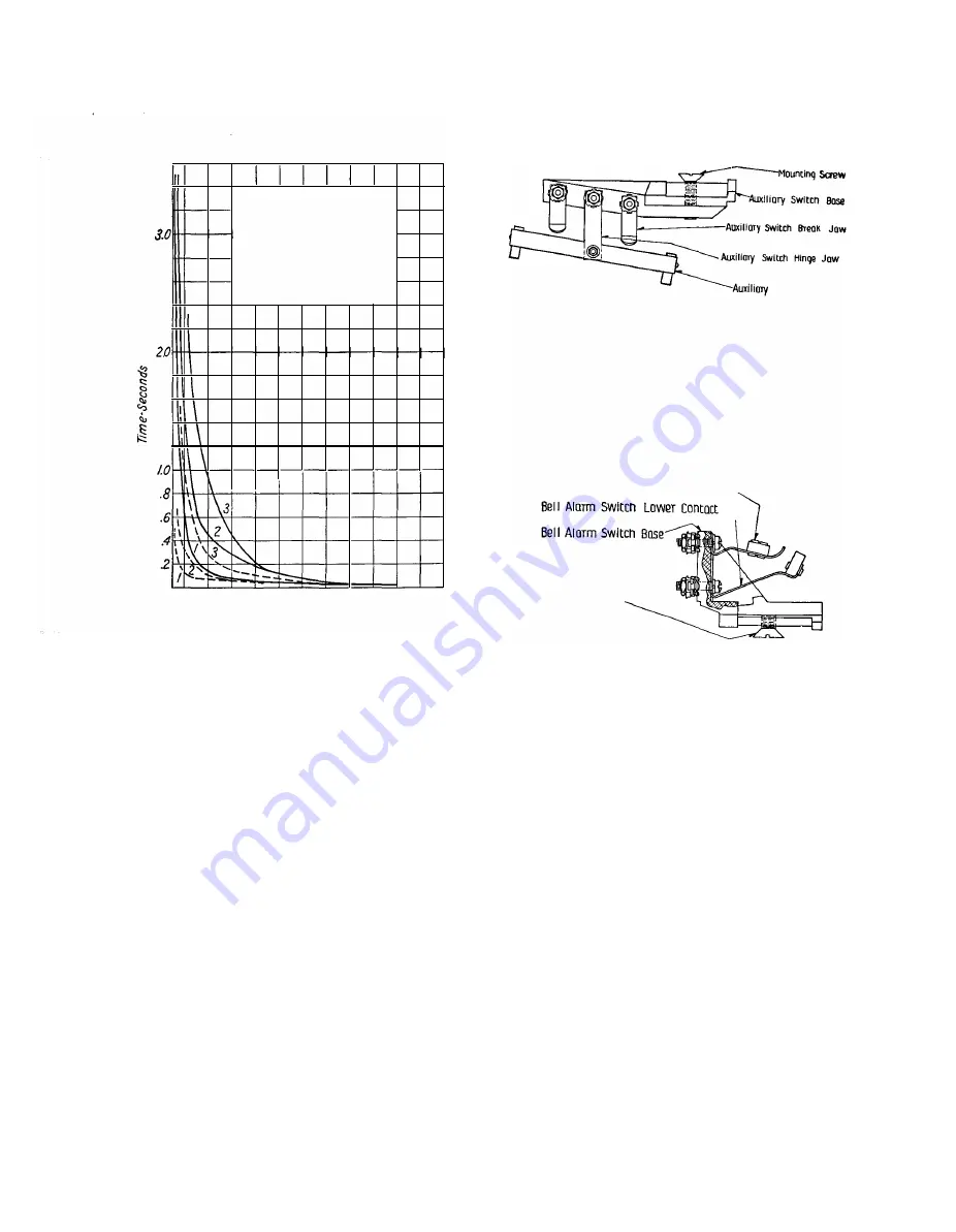
-Std.
Oil
--- Spcl. Low Temp. Oil
I. Minimum Time Delay
2. 50 "!o
Tim
e
Delay
3. Maximum Time Delqy
Temp.30°C.
SwitCh
Bloao
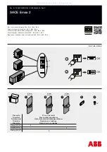
FIG. 16-AuxiLIARY SwiTCH
510 20
0
400
40
70
Current Amperes
800
1400
Current Per
cent
FIG. 15-CALIBRATION CuRvE
drawn downward by the tripping springs.
The armature will strike the tripping
arm which will raise the trigger on the
coverplate and allow the circuit-breaker
to open. The armature is not reset by
the circuit-breaker in opening and must
be reset by rotating the retrieving handle
to the left before the coil is re-energized.
The coil will burn out if the current is
flowing in the coil when the armature
is not in the retrieved position. The re
trieving handle must be released quickly
to secure positive tripping action, in case
the undervoltage coil is not energized.
If noise develops, the face of the
armature and magnetic circuit should
be inspected to. see that a good clean
seat is obtained when they are together.
Bell Alarm
Switch
Upper
Contact '-,
/00
Mountlnq Smw
2000
FIG. 17-BELL ALARM SWITCH
If necessary to clean this seat be careful
to leave it bearing over its entire area.
The coils are marked with their style
number, the style number of the series
resistor and the voltages and frequencies
on which they may be used. Reference
to these should be made in all corre
spondence regarding the device.
The
device is made for use with or without
resistor, depending upon whether it is
desired to trip the breaker by short
circuiting the undervoltage coil. When
this is done it is necessary to have a
resistor in the circuit in order that a
short-circuit on the control wiring will
not be obtained.
A screw adjustment is provided for
the opening springs by which it is pos-
13
sible to alter the drop-out point over a
considerable range.
The automatic retrieve undervoltage
mounts on the right-hand side of the
coverplate.
Its operation is identical
with that of the hand retrieve device
except that an additional reset lever
and spring are provided which will re
trieve the armature to the closed gap
position when the breaker opens. When
the breaker closes, a pin on the cover
plate trip lever engages this lever and
holds it back so that the armature is
free to trip the breaker. This under
voltage release should be energized from
the line side of the breaker.
See Fig.
27
for connections when a
rectox is supplied.
www
. ElectricalPartManuals
. com


