background image

24 | Westinghouse Outdoor Power Equipment, LLC

Westinghouse Outdoor Power Equipment, LLC | 25


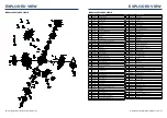
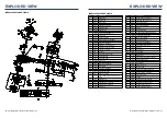
EXPLODED VIEW

IGEN2200 EXPLODED VIEW A

NO.

PART#

DESCRIPTION 

1

200204

CRANKCASE

2

205101

OIL SENSOR

3

91325

BOLT M6X12 

4

209903

WIRE CLIP

5

93501

CRANKCASE OIL SEAL 

6

93008

AXLE BEARING

7

200301

CRANKSHAFT

8

201201

PISTON

9

201601

PISTON RING ASSEMBLY

10

205501

PISTON PIN

11

201301

PISTON PIN RING

12

201503

CONNECTING ROD ASSEMBLY

13

206101

VALVE LIFTER

14

202001

CAMSHAFT ASSEMBLY

15

240904

CRANKCASE LOCATING PIN

16

96004

CRANKCASE SEAL WASHER

17

200101

CRANKCASE COVER

18

205601-

160

DIPSTICK

19

96005

CYLINDER HEAD GASKET

20

201001

CYLINDER HEAD

21

97101

SPARK PLUG

22

202101

INTAKE ROCKER ARM ASSEMBLY

23

202102

EXHAUST ROCKER ARM ASSEMBLY

24

202103

ROCKER ARM SHAFT

25

201802

AIR INTAKE SPRING LOWER SEAT

26

201701

INTAKE VALVE

27

205901

EXHAUST VALVE 

28

206001

VALVE SPRING 

29

201801

INTAKE VALVE SPRING SEAT

30

200801

VALVE LOCK CLIP

31

91023

DOUBLE END BOLT M6X92 

32

91002

DOUBLE END BOLT M6X32

33

201901

PUSH ROD

34

91339

BOLT M6X50

NO.

PART#

DESCRIPTION

35

96006

HEAD COVER SEAL WASHER

36

201101

CYLINDER HEAD COVER

37

200501

COVER

38

97502

MAGNETO IGNITER

39

209901

SEALING RUBBER

40

91330

BOLT M6X20

41

200401

FLYWHEEL ASSEMBLY

42

90014

NUT  M12

43

204701

STARTER ASSEMBLY

43.1 5323

START PULL PLATE

44

91805

CROSS GROOVED DISC HEAD BOLTS  M3X8

45

91329

BOLTS M6X16 

46

96007

JOINT BLOCK GASKET

47

202301

CARBURETOR CONNECTION BLOCK

48

96121

CARBURETOR GASKET

49

202801

CARBURETOR ASSEMBLY

50

92239

BOLTS M3*8

51

201104

BREATHING BOARD GASKET

52

209906

STEPPING MOTOR COVER

53

96009

AIR FILTER GASKET

54

202901

AIR CLEANER ASSEMBLY

54.1 5291

AIR FILTER ELEMENT

55

90016

NUT  M6

56

752007

STEPPER MOTOR

57

95614

CYLINDER HEAD BREATHER TUBE

58

202502

MUFFLER ENCLOSURE

59

209902

COVER RETAINING CARD

60

203704

MUFFLER ASSEMBLY

60.1 6789

SPARK ARRESTER

61

97501

IGNITION COIL ASSEMBLY

62

96008

EXHAUST SEAL WASHER

63

94407

FUEL LINE CLAMP

64

201103

CYLINDER HEAD BREATHING PLATE

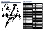
EXPLODED VIEW

IGEN2200 EXPLODED VIEW A

Summary of Contents for iGen2200

Page 1: ...CT TO THE STORE If you have questions or need assistance please call customer service at 855 944 3571 iGen2200 Digital Inverter Generator 1800 Running Watts 2200 Peak Watts iGen2500 Digital Inverter G...

Page 2: ...limited by such factors as fuel BTU content ambient temperature altitude engine conditions etc Maximum power decreases about 3 5 for each 1 000 feet above sea level and will also decrease about 1 for...

Page 3: ...spaces INCORRECT USAGE Do not operate in any of the following locations Near any door window or vent Garage Basement Crawl Space Living Area Attic Entry Way Porch Mudroom SAFETY SAFETY DEFINITIONS Th...

Page 4: ...not allow the generator s gas tank to overflow when filling Shut down the engine and allow it to cool for five minutes before adding gasoline or oil to the generator Never remove the fuel cap when the...

Page 5: ...sed to turn fuel valve to the run choke or OFF position 3 Output Ready LED Illuminates when the generator is operating normally Indicates the generator is producing electrical power at the receptacles...

Page 6: ...not overfill Fill only to the red maximum fill ring on the fuel screen filter visible in the filler neck Maximum Fuel Level Screen Filter Fuel Cap 5 Install the fuel cap Tighten until a click is hear...

Page 7: ...or or electrical appliance in wet conditions such as rain or snow or near a pool or sprinkler system or when your hands are wet could result in electrocution WARNING Fire hazard Only operate the gener...

Page 8: ...stimated Running Watts Estimated Starting Watts Incandescent Lights 4 Quantity x 75 Watts 300 0 TV Tube Type 300 0 Sump Pump 1 3 hp 800 1300 Refrigerator or Freezer 700 2200 Well Pump 1 3 hp 1000 2000...

Page 9: ...s before stopping the generators TRANSPORTING Allow the generator to cool a minimum of 30 minutes before transporting Replace all protective covers on the generator control panel Only use the generato...

Page 10: ...he full mark on dipstick 7 Replace the oil dipstick and hand tighten 8 Install the engine service cover MAINTENANCE MAINTENANCE SCHEDULE Regular maintenance will improve performance and extend the ser...

Page 11: ...rator for two to six months drain the float bowl to prevent gum and varnish buildup in the carburetor MAINTENANCE ENGINE OIL CHANGE WARNING Accidental start up Remove the spark plug boot from the spar...

Page 12: ...1 MAINTENANCE DRAINING THE FLOAT BOWL 1 Remove the engine service cover 2 Locate the drain hose extending from the bottom of the carburetor float bowl Suitable Fuel Container Float Bowl Drain Screw Dr...

Page 13: ...0 200801 VALVE LOCK CLIP 31 91023 DOUBLE END BOLT M6X92 32 91002 DOUBLE END BOLT M6X32 33 201901 PUSH ROD 34 91339 BOLT M6X50 NO PART DESCRIPTION 35 96006 HEAD COVER SEAL WASHER 36 201101 CYLINDER HEA...

Page 14: ...AME SHOCK ABSORBER PAD 33 90027 NUT 16X16X5_M6 34 500002 BOTTOM PLATE 35 500317 SHOCK ABSORPTION BEARING 36 500040 MOTOR VIBRATION DAMPING PAD 37 500035 ENGINE VIBRATION DAMPING PADS NO PART DESCRIPTI...

Page 15: ...32 96121 CARBURETOR PAPER PAD 33 202805 CARBURETOR ASSEMBLY 34 92239 BOLTS M3 8 NO PART DESCRIPTION 35 91023 DOUBLE END BOLT M6X92 36 209906 STEPPING MOTOR COVER 37 96009 AIR FILTER GASKET 38 202902 A...

Page 16: ...L TANK 39 500032 OIL CHANNEL 40 500314 FILTER 41 500308 FUEL TANK CAP 42 99519 FLAT PAD 43 500029 332 RIGHT FRAME NO PART DESCRIPTION 44 500297 332C RIGHT PANEL 45 500019 052 PULL ROPE GUIDE PLATE 46...

Page 17: ...32 Westinghouse Outdoor Power Equipment LLC Westinghouse Outdoor Power Equipment LLC 33 SCHEMATICS IGEN2500 SCHEMATICS SCHEMATICS IGEN2200 SCHEMATICS...

Reviews: