12 | Westinghouse Outdoor Power Equipment, LLC
Westinghouse Outdoor Power Equipment, LLC | 13
OPERATION
BREAK-IN PERIOD
For proper break-in, do not exceed 50% of the rated
running watts (iGen2200: 900 watts / iGen2500: 1100
watts) during the first five hours of operation.
Vary the load occasionally to allow stator windings to heat
and cool and help seat the piston rings.
FREQUENCY OF USE
If the generator will be used on an infrequent or intermittent
basis (more than one month before next use), refer to the
Storage section of this manual for information regarding
fuel deterioration.
BEFORE STARTING THE GENERATOR
Verify that:
• The generator is placed in an safe, appropriate location.
•
The generator is on a dry, flat, and level surface.
•
The engine is filled with oil.
• Gasoline is in the fuel tank.
• All loads are disconnected.
• The ECO switch is in the OFF position.
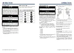
DANGER
Fire and explosion hazard. DO NOT move or tip the
generator during operation.
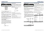
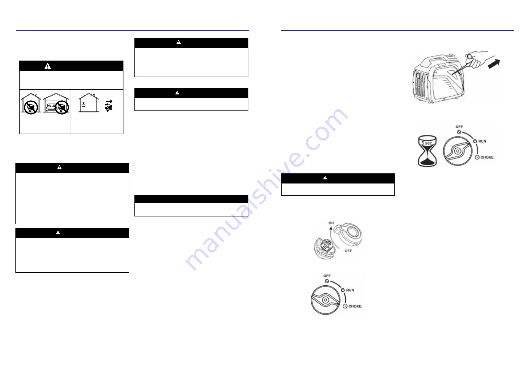
STARTING THE ENGINE
1.
Turn the fuel cap vent to the ON position (iGen2200
only).
2.
Turn the fuel switch to the choke position.
Note:
The generator can be started from the Run position
if warm from operation.
3.
Firmly grasp and pull the recoil handle slowly until you
feel increased resistance, then pull rapidly.
4.
After the engine starts, turn the fuel switch to the RUN
position.
STOPPING THE ENGINE
1.
Turn off and unplug all connected electrical loads.
Never start or stop the generator with electrical devices
plugged in or turned on.
2.
Let the generator run with no load for several minutes
to stabilize internal temperatures of the engine and
generator.
3.
Turn the fuel switch to the OFF position.
4.
Allow the engine to cool, then turn the fuel cap vent to
the OFF position (iGen2200 only).
Note:
If there is an emergency and the inverter must be
stopped quickly, immediately move the fuel switch
to the OFF position.
OPERATION
GENERATOR LOCATION
Read and understand all safety information before starting
the generator.
Using a generator indoors CAN KILL YOU IN MINUTES.
Generator exhaust contains carbon monoxide. This is a
poison you cannot see or smell.
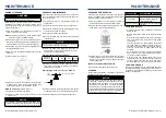
DANGER
NEVER use inside a home
or garage, EVEN IF doors
and windows are open.
Only use OUTSIDE and far
away from windows, doors,
and vents.
NEVER operate the generator inside any building, including
garages, basements, crawlspaces, sheds, enclosure, or
compartment, including the generator compartment of a
recreational vehicle.
DANGER
Electrocution hazard. Never use the generator in a
location that is wet or damp. Never expose the generator
to rain, snow, water spray, or standing water while in
use. Protect the generator from all hazardous weather
conditions. Moisture or ice can cause a short circuit
or other malfunction in the electrical circuit. Using a
generator or electrical appliance in wet conditions, such
as rain or snow, or near a pool or sprinkler system, or
when your hands are wet, could result in electrocution
WARNING
Fire hazard. Only operate the generator on a solid, level
surface. Operating the generator on a surface with loose
material such as sand or grass clippings can cause debris
to be ingested by the generator that could block cooling
vents or the air intake system. Allow the generator to
cool for 30 minutes before transport or storage.
The generator should be on a flat, level surface at all times
(Even while not in operation). The generator must have
at least 5 ft. (1.5 m) of clearance from all combustible
material.
Do not operate the generator in the back of a SUV, camper,
trailer, truck bed (regular, flat, or otherwise), under stairs,
next to walls or buildings, or in any other location that will
not allow for adequate cooling of the generator and/or the
muffler. DO NOT contain generators during operation.
DANGER
Asphyxiation hazard. Place the generator in a well-
ventilated area. DO NOT place the generator near vents
or intakes where exhaust fumes could be drawn into
occupied or confined spaces. Carefully consider wind
and air currents when positioning generator.
GROUNDING
WARNING
Shock hazard. Failure to properly ground the generator
can result in electric shock.
The generator neutral is floating. The generator ground
terminal is connected to the frame of the generator, the
metal non-current-carrying parts of the generator, and
the ground terminals of each receptacle. The generator
(stator winding) is isolated from the frame and from the
AC receptacle ground pin. Electrical devices that require
a grounded receptacle pin connection may not function
properly.
If this generator will be used only with cord and plug
equipment connected to the receptacles mounted on the
generator, National Electric Code does not require that
the unit be grounded. However, other methods of using
the generator may require grounding to reduce the risk of
shock or electrocution.
NOTICE
Only use grounded 3-prong extension cords, tools, and
appliances, or double-insulated tools and appliances.
Before using the ground terminal, consult a qualified
electrician, electrical inspector, or local agency having
jurisdiction for local codes or ordinances that apply to the
intended use of the generator.
HIGH ALTITUDE OPERATION
Engine power is reduced the higher you operate above sea
level. Output will be reduced approximately 3.5% for every
1000 feet of increased altitude from sea level.
High altitude adjustment is required for operation at
altitudes over 5,000 ft. (1524 m). Operation without this
adjustment will cause decreased performance, increased
fuel consumption, and increased emissions. Operation of
the engine at altitudes below 2,000 ft. (762 m) with the high
altitude kit is not recommended.
High Altitude Carburetor Kit, iGen2200: Part# 518900
High Altitude Carburetor Kit, iGen2500: Part# 518922-1


