background image

Westinghouse Outdoor Power Equipment, LLC | 19

OPERATION

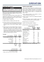
GENERATOR CAPACITY

NOTICE

DO NOT

 overload the generator’s capacity. Exceeding 

the generator’s wattage/amperage capacity can damage 

the generator and/or electrical devices connected to it.

Make sure the generator can supply enough continuous 

(running) and surge (starting) watts for the items you will 

power at the same time. 
The total power requirements (Volts x Amps = Watts) of all 

appliances connected must be considered. Appliance and 

power tool manufacturers usually list rating information 

near the model or serial number.
To determine power requirements:

1. 

Select the items you will power at the same time.

2. 

Total the continuous (running) watts of these items. This 

is the amount of power the generator must produce 

to keep the items running. See the wattage reference 

chart.

3. 

Estimate how many surge (starting) watts you will need. 

Surge wattage is the short burst of power needed to 

start electric motor-driven tools or appliances such as a 

circular saw or refrigerator. Because not all motors start 

at the same time, total surge watts can be estimated by 

adding only the item(s) with the highest additional surge 

watts to the total rated watts from step 2.

Example:

Tool or Appliance

Running 

Watts*

Starting 

Watts*

RV Air Conditioner (11,000 BTU)

1010

1600

TV (Tube Type)

300

0

RV Refrigerator

180

600

Radio

200

0

Light (75 Watts)

300

0

Coffee Maker

600

0

2590 Total  

Running 

Watts*

1600 

Highest 

Starting 

Watts*

Total Running Watts

2590

Highest Starting Watts

+ 1600

Total Starting Watts Needed

4190

*Wattages listed are approximate. Verify actual wattage.

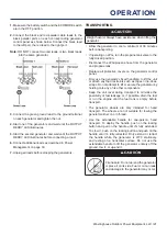
POWER MANAGEMENT

To prolong the life of the generator and attached devices, 

use care when adding electrical loads to the generator. 

There should be nothing connected to the generator 

outlets before starting the engine. The correct and safe 

way to manage generator power is to sequentially add 

loads as follows:

1. 

With nothing connected to the generator, start the 

engine as described in this manual.

2. 

Plug in and turn on the first load, preferably the largest 

load you have.

3. 

Permit the generator output to stabilize (engine runs 

smoothly and attached device operates properly).

4. 

Plug in and turn on the next load.

5. 

Again, permit the generator to stabilize.

6. 

Repeat steps 4 and 5 for each additional load.

Wattage Reference

Tool or Appliance

Estimated 

Running 

Watts*

Estimated 

Starting 

Watts*

Incandescent Lights  

(4 Quantity x 75 Watts)

300

0

TV (Tube Type)

300

0

Sump Pump (1/3 hp)

800

1300

Refrigerator or Freezer

700

2200

Well Pump (1/3 hp)

1000

2000

Furnace (1/2 hp)

800

2350

Radio

200

0

Drill (3/8”, 4 amps)

440

600

Circular Saw 

(Heavy Duty, 7-1/4”)

1400

2300

Miter Saw (10”)

1800

1800

Table Saw (10”)

2000

2000

*Wattages listed are approximate. Verify actual wattage.

Summary of Contents for iGen4500DFc

Page 1: ...IS PRODUCT TO THE STORE If you have questions or need assistance please call customer service at 855 944 3571 iGen4500DFc Digital Inverter Generator Gasoline 3700 Running Watts 4500 Peak Watts Propane...

Page 2: ...THESE INSTRUCTIONS TABLE OF CONTENTS DISCLAIMERS 2 ALL RIGHTS RESERVED 2 INTRODUCTION SPECIFICATIONS 3 SAFETY SAFETY DEFINITIONS 4 SAFETY SYMBOLS 4 SAFETY INSTRUCTIONS 5 CO SENSOR 9 ACTION LABEL 9 CO...

Page 3: ...is exposed to temperatures outside of this range during storage it should be brought back within this range before operation This product must always be operated outdoors in a well ventilated area an...

Page 4: ...es a hazardous situation which if not avoided could result in death or serious injury Indicates a hazardous situation which if not avoided could result in minor or moderate injury NOTICE Indicates a s...

Page 5: ...e laws and electrical codes Electrocution hazard Never use the generator in a location that is wet or damp Never expose the generator to rain snow water spray or standing water while in use Protect th...

Page 6: ...d water A transfer switch must be installed by a licensed electrician approved by the authority having jurisdiction The installation must comply with all applicable laws and electrical codes FUEL SAFE...

Page 7: ...ator is not used the regulator that is attached to the fuel tank The pressure as measured at the regulator mounted to the generator must be 7 to 14 of water column A certified plumber must ensure that...

Page 8: ...8 Westinghouse Outdoor Power Equipment LLC SAFETY SAFETY LABELS AND DECALS...

Page 9: ...all battery powered carbon monoxide alarm s in your home Automatic shutoff accompanied with a flashing RED light in the CO Sensor portion of the control panel is an indication that the generator was i...

Page 10: ...ushing the locking button 5 Carry Handles Built in handles allow easy two person transport 6 Recoil Handle Pull the recoil handle to manually start the engine 7 Control Panel The control panel contain...

Page 11: ...ed to select gas or propane operation 11 LPG Propane Inlet Connects a propane tank with the included LPG propane hose 12 Battery Charging Port Used to charge the battery with the included battery char...

Page 12: ...r service team at service wpowereq com or call 1 855 944 3571 INITIAL OIL FILL NOTICE THIS GENERATOR HAS BEEN SHIPPED WITHOUT OIL Do not attempt to crank or start engine before it has been properly se...

Page 13: ...he fuel system Follow the manufacturer s instructions for use ALWAYS mix the correct amount of fuel stabilizer to gasoline in an approved gasoline container before fueling the generator Run the genera...

Page 14: ...nk valve and attach the other end of the hose to the LPG propane connector on the tank Hand tighten 7 Turn the propane tank valve to the fully open position Check all connections for leaks by wetting...

Page 15: ...NOT place the generator near vents or intakes where exhaust fumes could be drawn into occupied or confined spaces Carefully consider wind and air currents when positioning the generator GROUNDING Sho...

Page 16: ...r light will flash green 3 Push the ON button on the remote start key fob It will pair with generator automatically and the start indicator light on the generator will stop flashing FUEL SELECTOR SWIT...

Page 17: ...if a propane tank is connected to the generator BEFORE operation GASOLINE TO PROPANE IMPORTANT Load capacity is reduced when running on propane Make sure the generator can supply enough running and s...

Page 18: ...c light Turn ECO MODE OFF when powering large surge loads such as an air conditioner or electric pump To turn on ECO MODE verify that the OUTPUT READY LED is illuminated green then push the switch to...

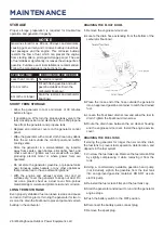
Page 19: ...Conditioner 11 000 BTU 1010 1600 TV Tube Type 300 0 RV Refrigerator 180 600 Radio 200 0 Light 75 Watts 300 0 Coffee Maker 600 0 2590 Total Running Watts 1600 Highest Starting Watts Total Running Watt...

Page 20: ...iance is in good working order Faulty appliances or power cords can create a potential for electric shock Make sure the electrical rating of the tool or appliance does not exceed the rated power of th...

Page 21: ...position Disconnect the LPG propane hose from the generator and propane tank Replace all protective covers on the generator control panel Only use the generator s fixed handle s to lift the unit or a...

Page 22: ...ler MAINTENANCE REPLACEMENT PARTS Description Part Number Foam air filter 5691 Oil drain plug crush washer 94007 Spark arrestor 6790 Battery 511019 Spark plug ENGINE SERVICE COVER Remove the engine se...

Page 23: ...with engine oil Wear protective clothing and equipment Wash all exposed skin with soap and water NOTICE Always use the specified engine oil Failure to use the specified engine oil can cause accelerat...

Page 24: ...fill Maximum oil capacity 0 63 US qt 0 60 L 9 Replace the dipstick and hand tighten 10 Connect the spark plug wire and install the engine service cover NOTICE Do not pollute Follow the guidelines of t...

Page 25: ...not regularly run the generator charge the battery overnight once a month to keep it ready for use Charge the battery in a dry location 1 Plug the charger into the battery charging port on the control...

Page 26: ...r propane tanks near furnaces water heaters or any other appliances that produce heat or have automatic ignitions With the engine and exhaust system cool and all surfaces dry cover the generator to ke...

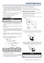
Page 27: ...ot rotate the engine 360 5 Insert a feeler gauge between the rocker arm and the valve stem to measure valve clearance Intake Valve Exhaust Valve Valve Clearance 0 0031 0 0047 in 0 08 0 12 mm 0 0051 0...

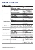
Page 28: ...stored without treating or draining gasoline or refueled with bad gasoline Drain the fuel tank Refuel with fresh gasoline Fuel system malfunction fuel pump failure ignition malfunction valves stuck et...

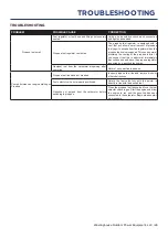
Page 29: ...ediately discontinue use and have the propane regulator inspected by a qualified technician Residual fuel from the carburetor dispersing after operation Normal no correction is needed Poor performance...

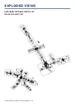
Page 30: ...30 Westinghouse Outdoor Power Equipment LLC EXPLODED VIEW AND PARTS LIST ENGINE EXPLODED VIEW EXPLODED VIEWS...

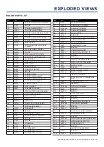
Page 31: ...G MOTOR ASSEMBLY 4 5 91333 BOLT M6 4 6 91334 BOLT M6 4 7 245113 OIL SENSOR 4 8 91329 BOLT M6 4 9 91816 OIL DRAIN BOLT 4 10 94007 OIL DRAIN BOLT WASHER 4 11 94035 OIL DRAIN BOLT WASHER NO Code Descript...

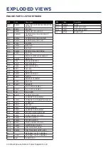
Page 32: ...0057 MUFFLER COVER 20 240511 SHIELD 21 BRACKET ASSEMBLY 21 1 91330 BOLT M6 21 2 249917 BRACKET 22 AIR FILTER ASSEMBLY 22 1 332901 AIR FILTER ASSEMBLY 22 1 1 5691 AIR FILTER 22 2 95918 CONNECTING PIPE...

Page 33: ...Westinghouse Outdoor Power Equipment LLC 33 GENERATOR EXPLODED VIEW EXPLODED VIEWS...

Page 34: ...EL REAR COVER ASSEMBLY 7 1 503016 PANEL REAR COVER 7 2 92078 SCREW M6 7 3 505027 WIRE SLEEVE NO Code Description 8 100110012 PANEL KIT ASSEMBLY 8 1 503802 PANEL ASSEMBLY 8 1 1 9222 ROCKER SWITCH 8 1 2...

Page 35: ...03043 BRACKET 15 7 95016 CARBON CANISTER AND AIR FILTER CONNECTING PIPE 16 BRACKET ASSEMBLY 16 1 91325 BOLT M6 16 2 503006 LIFTER 16 3 503008 BRACKET 16 4 503009 HANDLE 16 5 503042 BRACKET NO Code Des...

Page 36: ...VALVE 19 14 545332 PRESSURE REDUCING VALVE 19 15 96120 GASKET 19 16 503127 OURLET CONNECTOR 19 17 517907 LOW PRESSURE HOSE 20 503805 DEPUTY WIRING HARNESS 21 503082 BELLOWS 22 503808 DEPUTY WIRING HAR...

Page 37: ...Westinghouse Outdoor Power Equipment LLC 37 SCHEMATICS SCHEMATICS...

Reviews: