background image

T Y P E S  CA- 1 6  AND CA-26  R E L AYS 

····"·· 

CIITACt•  •nu 

lOTI!: 

WIT"  IEI.AT I'fE  IISTAI• 
TAJEOUS  POUIITIU 

.U 

ltiM· 

TIE  AMI>EIE 

lUllS  I I   TNE  PAllED 
IUTIA IIUI  tOILS  ADD 

TO 

NOOI.It£  MAXIMUM 

naquE. 

un  ... a� 

( ...

'D'IlH- BMII' 

(f.'�} 

187A434 

Fig. 

5. 

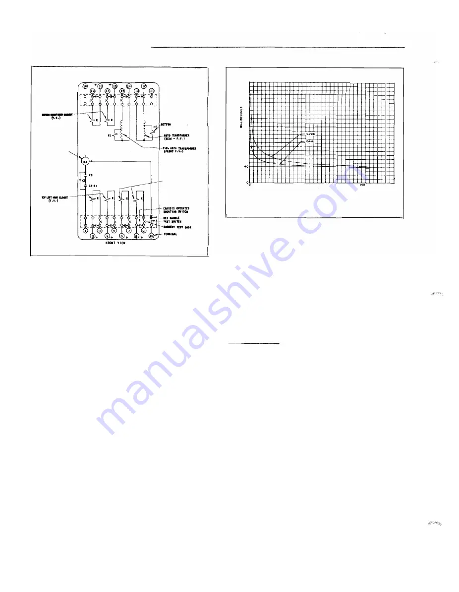
Internal  Schematic  of  the  Type  CA- 1 6   B us  Relay 

with  a  Sensitive  Fault Detector 

switch.  When  the  switch  clos e s ,   the  moving  c ontacts 

bridge  two  stationary  c ontacts ,  completing  the  trip 
circuit .  Also  during  this  operation,  two  fingers  o n  
the  armature  deflect  a  spring  located  on  the  front  of 
the  switch  which allows  the operation  indic ator target 
to  drop.  The  target  is  reset  from  the  outside  of  the 
case  by  a push  rod  located at  the  bottom of the c over. 

A  core  screw  accessible  from  the top of the switch 

provides the  adjustable  p ick-up range. 

O P E R A T I O N  

The  types  C A- 16  and  CA-26  rel ays  are  induction 

disc  relays  with  four  electromagnets  mounted  on  two 
discs  that  are  fastened  on  a  common  shaft.  One  of 

the  elect romagnets  is  the  op erating  element  while 

the  other  three  are  restraint  elements.  The re straint 
elements  are  energized  from  the  secondaries  of c ur­
rent  transformers  connected  to  the  b us ,   and  the 

operating  circuit  is  energized  in  accordance  with  the 

current  flowing  in  the  differential  c onnection  of  the 
current  transformers . 

A  current  of 

an1peres  in  at  terminal  1 8   and out of 

terminal  1�  will  produce  a  definite  amount  of  re­
straining  torque  (see  Fig. 

3 . )  

Similarly,  a  c urrent  of 

amp ere s  flowing  in  at  terminal  1 6   and  out  of ter­

minal  17  will  produce  an  e qual  amount  of  torque .  If 
both  of  these  currents  flow  at  the  same  time  with the 

240 

200 

160 

� 

120 


� 

ll 

00 

� 

20 

40 

60 

80 

100 

120 

160 

OPERATING  CURRENT  IN 

AMPERES 

Curve 

5379 56 

Fig.  6.  Typ ical  Time  Curves  of  the  CA- 1 6   and  CA-26  dif­

ferential  Relays 

polarity  as  indicated  above ,   their  effect  will  be  addi­

tive  and  they  will  produce  the  same  torque  as though 
10 amperes  were  flowing  in terminal  16  and  out  of ter­

minal  1 7.  Conversely ,  if  e qu al  currents  flow  in  these 

two  coil s ,   but  in  opposite  directions,  their  ampere 
turns  will  cancel  and  no torque  will  be produced.  The 

same  rel ationship  applies  for  the  p aired  coils  of the 

other two restraining  units  of the relay. 

C H A R A C T E R !  S T E R I  C S  

CA- 1 6   B u s  

Relay 

This  relay  has  v ariable  percentage  characteristics 

which  means  that  the  operating  coil  current required 

to  close  the  relay  contacts,  expressed  in  p er  cent  of 

the  total  restraint  current ,  v arie s  with  the m agnitude 

of  the  restraint  current.  The rel ay  sensitivity  is  high, 
corresponding  to  a  low  percentage  ratio ,  at  light  c ur­

rents,  and  its  sensitivity  is  low,  c orresponding to 
high  percentage  unbal ance ,   at  high  currents.  The re ­

lay  is  made  sensitive  at  l ow  currents  in  order  to  de ­

teet  light  internal  faults  on  the  bus  being p rotecte d .  

At  the  same  time,  however,  its  reduced  sensitivity  at 

the  higher  c urrents  allows  the  various  c urre nt  trans ­

formers  involved  to  depart  from  their  true  ratio  t o  a 

l arge  extent  w ithout  causing  false  tripping  of  the  re­

lay  for  external  faults. 

The  v ariable  percent age  characteristics  are  par­

tic ularly  advantageous  when severe  saturation  of  cur­
rent  transformers  is  caused  by  the  d-e  c omponent of 
asymmetrical  short  circuits.  In  the  case  of buses 

located  close  to  generating  stations  where  the  d-e 

components  decay  slowly,  the  breakdown 

in 

ratio  of 

the  current  transformers  will  be  much  greater than 

www 

. ElectricalPartManuals 

. com 

Summary of Contents for KAB

Page 1: ...t s is not recommend ed If this cannot be avoided the additional impedance from the auxiliary ct s and the high voltage which transformed by the auxiliary ct should be checked SUPERSEDES I L 41 337 4...

Page 2: ...pring adj uster is also held in place by a spring ty pe clamp With the contacts closed the electrical connec tion is made through the stationary contact housing 2 clamp to the mo ving contact through...

Page 3: ...overstress the insula tion A varistor is connected internally to reduce this voltage Figure 2 shows the electrical char acteristics of this device The overvoltage unit is a high speed device and will...

Page 4: ...ce Rs 0 93 n and one way l ead resistance to junction point RL 1 07D A SETTING OF VOL TAGE UNIT 4 a for 3 phase fault condition Rs t RL _l_r I VK 0 93 1 07 N from Fig 3 K 0 76 60000 l I 375 400 0 9 V...

Page 5: ...g enough to trip a breaker I L 41 337 4A BU R D E N The relay burden is approximately 2600 ohms in the tuned circuit However this burden is not seen by any of the CTS during normal operation or during...

Page 6: ...y be necessary to re adjust the overvoltage unit spring for the desired operate voltage 6 Overvoltage Unit V 1 The upper bearing screw should be screwed down until there is approximately 025 clear anc...

Page 7: ...he voltage should measure 175 volts ac 10 A high resistance voltmeter should be used R E N EWAL PAR T S Repair work can be done most satisfactorily at the factory However interchangeable parts can be...

Page 8: ...vv _ I _ _ _H t 0 0 LO ID t 0 0 0 0 q ci PEAK CURRENT AMPERES Fig 2a Typical Volt Ampere Characteristic of Varistor in Type KAB Relay Peak Value I I I I 0 I I II 349 7A22 Ol 1 c Vl 1J om o mOl O t m z...

Page 9: ...300 200 100 01 o V 0 1 AMPERES RMS Fig 2b Typical Volt Ampere Characteristic of Varistor in Type KAB Relay RMS I I v 10 Curve 619414 OJ l c V om n Tl mOJ O r m zC1 l r r3 l om mo r z r w w m w E l e...

Page 10: ...75 0 50 0 25 10 20 30 40 so 60 70 so 90 1 00 1 10 1 20 1 30 VR MARGIN FACTOR K IRs RLI t Fig 3 Margin Factor for V Unit Setting 1 40 1 50 I CJ j C tl om l I mCJ Oz m zc I j I r om I m e r Z n m 1 60...

Page 11: ...2 3 1 I 4 5 6 8 1 0 IJ I j I J 4U 3U zn I 7 1 J ll J I I I I I R S R L 5 0 I v r vy P As RL 0 75 1 0 1 j J t 1 5 6 7 8 10 15 20 30 40 50 60 70 80 100 IT UNIT SETTING AMPERES AMSl Fig 4 IT Unit Setting...

Page 12: ...L LOCKOUT RELAY 52 BREAKERS NOTE RELAY TERMINALS 8 9 810 SHOULD BE OPEN WHEN CLRCUIT BREAKER OR BREAKERS IS TO BE BYPASSED FOR MAINTENANCE OR WHEN ANY OTHER ABNORMAL SETUP IS TO BE MADE I T y_ I 8 _7_...

Page 13: ...DANCE BUS DlFFE R ENT lA L R ELAY L 4 1 3 _ 3 7 4A Gl t 0 IL Gl 01 0 I L E lz 0 J I 0 0 Gl E 0 0 Gi a 0 c u a N o o 0 Gi co t 0 0 u __ N S3l A 3VIIIl E Nil f 3d0 13 w w w E l e c t r i c a l P a r t M...

Page 14: ...SCIEW II FOR THICK fiAIIEL USE 6 TERNIMAL AIID IQINTING DETAILS li 18 STUD _ 190 32 SCREW FOR THICK PANEL USE 190 32 STUO 3 DIA IO IIOL S Olt CUT OUT J1 e 1 _DIA IJ KOU S flll 2 1 _ 1 110 12 m aaBrl...

Page 15: ...w w w E l e c t r i c a l P a r t M a n u a l s c o m...

Page 16: ...WESTINGHOUSE ELECTRIC CORPORATION RELAY INSTRUMENT DIVISION NEWARK N J Printed in U S A w w w E l e c t r i c a l P a r t M a n u a l s c o m...

Page 17: ...ed for transformer differential applications since it is too sensitive for overriding the inrush Likewise the CA 26 relay should not be used for bus protection with the four circuit bus connections of...

Page 18: ...T Y P ES CA 1 6 AND CA 26 R ELAYS ________________________ 2 w w w E l e c t r i c a l P a r t M a n u a l s c o m...

Page 19: ...uncing A Micarta disc is fastened to the bottom of the guide rod by 30TT OM RI HT AliD Elf Mfn F V l lkJI ATING ONTACTO SWITCH TOPLHTII 0 LE E T F 1 OTE WITH flATIH I SUN TAN OUS POLA ITI S AS h IIN T...

Page 20: ...I ao Ht 40 f t 0 20 0 60 80 100 120 140 160 OPERATING CURRENT IN AMPERES Curve 537956 Fig 6 Typical Time Curves of the CA 1 6 and CA 26 dif ferential Relays polarity as indicated above their effect w...

Page 21: ...amperes at 250 volts d e and will c arry this current long enough to trip breaker The indicating contactor switch has two tap s that provide a pick up setting of 0 2 or 2 amperes To change taps requi...

Page 22: ...9 connections where there are more than three sources the source CT s should be par allelled to reduce the effective number of source con nections to three The four circuit bus connec tions of Fig 8...

Page 23: ...N D M AI N T E N A N C E The proper adjustments to insure correct operatio n of this relay have been made at the factory Upon receipt of the relay no customer adjustments other than those covered und...

Page 24: ...it has no t arg et F Sens itive F a u lt Detec tor w h ere s upp l ied Apply current to terminals 14 and 15 of the re l ay The fault detector should operate between the limits of 0 14 2 to 0 158 amper...

Page 25: ...t clo se in the following times CA 16 52 5 milliseconds CA 26 72 5 milliseconds These times should be the average of 5 readings 5 lnd icating C o ntactor S w i t c h IC S Close the main relay contacts...

Page 26: ...e operating current to trip the relay for dif ferent restraint current for one restraint element as 1 0 well as for six restraint elements connected in series R E N E W A L P A R T S Rep air work c an...

Page 27: ...RENT CAN EXCEED TWICE TttE EXTERNAL FAUlT CURRENT SET P ICK UP EQUAL TO MAXIMUM EXTERNAL FAULT CURRENT 1 3 A c AUX CURREMT BALAMCE CURRENT TRAitS 87 i9 7 87 87 8 12 PHASE 2 SAME AS PH H o 15 POS r 1 I...

Page 28: ...25 16 q DIA HOLES FOR s ff r 32 Uftn J oo f 4_ PANEL CUTOUT DRI LLIJG FOI SEMI FLUSH MTG PAREL DRI LLIIIG OR CUTOUT FOR PRQJECTJOII MTG FROIIT Y I EW 57 D 7903 6 f Fig 15 Outline and Drilling for the...

Page 29: ...ed i ssue T _ h e CA 6 re lay sho o be u _ til zed for tra s form er differential appllcat iiJ i_ since It IS too se nsitive for overriding the i nrus h _ Likewise the C A 26 relay shoul d not be us e...

Page 30: ...T T YP ES CA 16 AND CA 26 R ELAYS _ ___________ _ _ _ _ _ _ __ _____ i c Ill a u Ill Cl 1 IJ 2 w w w E l e c t r i c a l P a r t M a n u a l s c o m...

Page 31: ...evented from causing contact bouncing A Mic arta disc is fastened to the bottom of the guide rod by BOTTOM R I GHT II I IID ELEMEIH F V IHD ICATIMG CONTA CTOR SWITCH CA U 00 CA 26 TOP LEFT ltAIID ELEM...

Page 32: ...2 CA 6 ll 00 40 20 40 60 80 100 120 160 OPERATING CURRENT IN AMPERES j_ _ _ _ _ _ _ _ _ _ Curve 537956 Fig 6 Typ ical Time Curves of the CA 1 6 and CA 26 dif ferential Relays polarity as indicated abo...

Page 33: ...reaker The indicating instantaneous trip contacts will safely close 30 amperes at 250 volts d e and will carry this current long enough to trip breaker The indicating contactor switch has two taps tha...

Page 34: ...s the source CT s should be par allelled to reduce the effective number of source con nections to three The four circuit bus connec tions of Fig 8 are not recommended to be used for bus protection wit...

Page 35: ...rrect operation of this relay have been made at the factory Upon receipt of the rel ay no customer adjustments other than those covered under SETTINGS should be required Ac ceptance C h ec k The follo...

Page 36: ...y suf ficient current to operate the liT F Sen s i t i ve F au l t D etec to r w here s u pp l ied Apply current to terminals 14 and 15 of the re lay The fault detector should operate between the limi...

Page 37: ...A 26 72 5 milliseconds These times should be the average of 5 readings 5 lnd icating C o n tactor Sw itc h IC S Close the main rela y contacts and pass sufficient d e current through the trip circuit...

Page 38: ...the operating current to trip the relay for dif ferent restraint current for one restraint element as 10 well as for six restraint elements connected in series R E N E W A L P A R T S Rep air work ca...

Page 39: ...SCREW 6 FOR THICK PMIEL USE t 18 STUD r r r I I I I I TEIMIIAL MD MOLI IITIIIG DETAILS TERMIUL MI BE 25 q Oi l IJ HOLES FOI 5 9 ff r I PANEL CUTOUT DRI LLI G FOR SEMI FUJSH MTG PAIEL DRI LLIRG OR CUTO...

Page 40: ...AESTUIIT COI L 6 TOP R H ELEM I CS I I D I CATIRG COlT SW l i T liD liST TRIP 86 AUX TRIPPIRG RELAY TYPE WL t USE WIIERE INTERNAL CURREKT CAM EXCEED TWICE TltE EXTERNAL FAULT CURRENT SET P I CK UP EQ...

Page 41: ...se the two way lead burden CON T E N T S This instruction leaflet plies to the following SUPERSEDES I L 41 337 26 Denotes change from superseded i ssue typ es of relays CA 16 Bus Differential Relay CA...

Page 42: ...TYPES CA 1 6 AND CA 26 R ELAYS 41 1 0 a 0 lJ Ill 41 Q 1 o i i 2 w w w E l e c t r i c a l P a r t M a n u a l s c o m...

Page 43: ...plunger BOTTOM R I GHT HAMO HEMEIIT F V INTERNAL SCHEMATIC I N O I CATIMG COMTACTOR SWITCH 1m ICS CA 16 IC l iT c u l_ TOP LEFT IIAIID ELEMEMT F V NOTE WITH RELATIVE INSTAN TANEOUS POLAR I T I ES AS S...

Page 44: ...14 I6C OPERATING CURRENT IN AMPERES Curve 537956 Fig 6 Typical Time Curves of the CA 1 6 and CA 26 dif ferential Relays rent transformers connected to the bus and the operating circuit is energized i...

Page 45: ...unit when a current transformer is severely satur ated by the d e component of an asymmetrical external fault current T r i p C ir c u it The main contacts will safely close 30 ampere s ElTEIIINAL SCH...

Page 46: ...these four sets of CT s to the rel ays p er Fig 8 The exception to this rule occurs when the application consists of three feeder groups Then Fig 9 applies With 3 feeder group s and more than 3 sourc...

Page 47: ...ench For detailed FT case information refer to L L 4 1 076 A D J U S T M E N T S A N D M Al N T E N A N C E The proper adjustments to insure correct operation of this relay have been made at the facto...

Page 48: ...0 The making of the contacts and target indic ation should occur at approximately the same instant Position the stationary contact for a minimum of 1 3 2 inch wipe The bridging moving contact should t...

Page 49: ...keep er of the permanent magnet until the contacts just clo se in the following times CA 16 52 5 milliseconds CA 26 72 5 milliseconds These times should be the average of 5 readings 5 lnd icating C o...

Page 50: ...relay for dif TEI MIMAL AIID MOUMTIIG DElliLS ferent restraint currents for one restraint element as well as for six restraint elements connected in series R E N E W A L P A R T S Rep air work can be...

Page 51: ...l t USE WHERE I NTERNAL CURRENT CAN EXCEED TlfiCE THE EXTERNAL FAULT CURRENT SET P I CX UP EQUAL TO MAX I EXTERUL FAULT CURRENT A A AUX CURREMT BALAMCE CURRENT TRAU POS I C S AUK CURRENT 2 R S T Ill I...

Page 52: ...WESTIN G H O USE E L E C T R I C C O R P O R ATI O N RELAY INSTRUMENT DIVISION NEWARK N J Printed in U S A w w w E l e c t r i c a l P a r t M a n u a l s c o m...

Page 53: ...N FOUR EQUIVALENT CIRCUITS DC TIME CONSTANT OF 0 6 CYCLES 0 01 Sec OR MORE The same requirements as in A apply How S UPERSEDES I L 41 337 1C Denotes ch ange from superseded i ssue ever consideration m...

Page 54: ...pper type device A magnetic armature to which 2 TOP FKOtH El f 4ENT F INTERNAL SCHEMATIC TOP REAR ELEMENT F Y J J 1NO I CAf l MG COnfACTOR Sifil fCH IMOICATING ICS J I C I l l IMSTAn TArtEO JS TRIP Ai...

Page 55: ...unt of restraining w _J 0 0 w _J 0 0 r 20 I I I l s l i It _ 0 o 20 40 60 80 NET TORQUE IN CENTIMETER GRAMS Curve 235496 Fig 4 Typical Differential Unit Time Curve torque as indicated in Fig 3 Similar...

Page 56: ...rmers will be much greater than would ever be e xpected from a consideration of the usual ratio curves of the current transformers involved CHARACT E RISTICS There are no taps inside the relay case Ta...

Page 57: ...S POs DEV I CE NUMBER CHART PH 1 87 PERCENTAGE D IFFERENTIAL RELAY TYPE CA 6 r r y TO BREAKER TR I P CO I LS NEG _ _ _ _ _ _ _ _ _ _ _ _ ICS I ND I CATING COMTACTOR SWI TCH OP OPERATI NG CO I L R PA I...

Page 58: ...PH 3 87 PERCENTAGE DtFFERENTIAL RELAY TYPE CA 6 ICS I ND I CA T I N G CONTACTOR SWI TCH OP OPERATING COI L R PA I RED RESTRA I NT COI L TOP FRONT ELENENT S PA I RED RESTRA INT CO I L BOTTOM REAR ELEM...

Page 59: ...O I LS 87 PERCENTAGE D I FFERENT IAL RELAY TYPE CA 6 ICS I ND I CAT I NG CONTACTOR SW I TCK OP OPERATING CO I L R PA I RED RESTRA INT CO I L TOP FRONT ELEMENT S PA I RED RESTRA I NT CO I L 80T TOI4 RE...

Page 60: ...SW I TCH OP OPERATINu CO I L R PA I RED R ESTRA INT CO I L TOP FRONT ELEMENT s PA I RED RESTRA I N T CO I L BOTTOM REAR ELEMENT T PA I RED RESTRA I NT CO I L BOTTOM FRONT ELEMENT PH 1 TYPE CA 6 IN TY...

Page 61: ...der that the relay maybe given a higher minimum trip setting as noted under Ad justments and Maintenance TRIP CIRCUIT The main contact will safely close 30 amperes at 250 volts d e and the seal in con...

Page 62: ...ed 5 of the total phase or ground fault cur rent with normal bus connections In paralleling current transformers for the feeder group or groups the load current distribution should be examined to insu...

Page 63: ...rces if there are less than 8 equivalent circuits 3 Avoid pairing the two largest sources 4 If feasible parallel matched current trans formers In case IV with two feeder groups one of the restraint el...

Page 64: ...12 of pick up desired It is recommended that a pickup of 100 amperes be used I N S TA L L A T I O N Th e relays should be mounted o n switchboard panels or their equivalent in a location free from dir...

Page 65: ...ommended for this purpose The use of abrasive material for clean ing contacts is not recommend ed because of the danger of embedding small particles in the face of the soft silver and thus impairing t...

Page 66: ...W FOR T H I C K PA N E L U S 1 90 U STUD T E R M I N A L AN D M O U N T I N G D ETA I LS N OTE ALL OIME N SIONS Ito I N C I IE I t D I A 4 H O L E S O R I S 2 2 MT S C R Ew5 PA N E L C UT O UT D R I L...

Page 67: ...6 Relay Without Case Rear View J Top Rear Operating Element 2 Stationary Contact 3 Moving Contact 4 Control Element 2 Bottom Rear Restraining Element Spring Assembly 5 Bottom Front Restraining Element...

Page 68: ...W E S T I N G H O U S E E L E C T R I C C O R P O R A T I O N R E LAY D E PA RTM E N T N EWA R K N J Printed in U S A w w w E l e c t r i c a l P a r t M a n u a l s c o m...

Page 69: ...l 337 3A Denotes change from superseded i ssue The CA l relay should not be utilized for transformer differential applications Likewise the O A 26 relay should not be used for bus p rotection with the...

Page 70: ...N Fig 1 Types CA 1 6 Relay front view Fig 2 Typ s CA 1 6 Relay rear view t m n I 0 z 0 n p 0 tl m r E l e c t r i c a l P a r t M a n u a l s c...

Page 71: ...remain s stationary Thus a c vibrations of the plunger are prevented from c ausing contact bouncing A Micarta disc is fastened to the bottom of the guide rod by BOTTOf I RIGHT IIA ND HEMEMT F V TOP L...

Page 72: ...60 80 100 120 140 160 OPERATING CURRENT IN AMPERES Curve 537956 Fig 6 Typical Time Curves of the CA 1 6 and CA 26 dif ferential Relays polarity as indicated above their effect will be addi tive and th...

Page 73: ...stantaneous trip contacts will safely close 30 amperes at 250 volts d e and will carry this current long enough to trip breaker The indic ating contactor switch has two taps that provide a pick up set...

Page 74: ...Fig 9 connections where there are more than three sources the source CT s should be par alleled to reduce the effective number of source con nections to three The four circuit bus connec tions of Fig...

Page 75: ...ion of this relay have been made at the factory Upon receipt of the relay no customer adjustments other than those covered under SETTINGS should be required Ac ceptance C h ec k The following check is...

Page 76: ...RESTRA INT COH IM TOP L EL 11 PE T PAIRED RESTUIIT COI L n 26 TOP R M EL 11 I CS I I D I CATIIG COlT SW I IT IIO liST TR I P 116 AUX TI IPPIIG RELAY TYPE Wl t USE wrtERE IMTEINAL CURRENT CAM EXCEED T...

Page 77: ...AN FOUR EQUIVALENT CIRCUITS DC TIME CONSTANT OF 0 6 CYCLES 0 01 Sec OR MORE The same requirements as in A apply How S UPERSEDES I L 41 337 1C Denotes ch ange from superseded i ssue ever consideration...

Page 78: ...ntact is made thru the spiral spring to the spring adjuster INDICATING CONTACTOR SWITCH UNIT ICS The d e indicating contactor switch is a small clapper type device A magnetic armature to which 2 INTER...

Page 79: ...Curve 235496 Fig 4 Typical Differential Unit Time Curve torque as indicated in Fig 3 Similarly a current of 5 amperes flowing in at termiRal 16 and out of terminal 17 will produce an equal amount of...

Page 80: ...al ratio curves of the current transformers involved CHARACT E RISTICS There are no taps inside the relay case Taps 4 controlling the sensitivity of the relay are incorpor ated in the external current...

Page 81: ...CENTAGE D I FFERENTIAl REl AY TYPE CA 6 r r y TO BREAKER TR I P CO I LS NEG _ ICS I ND I CATI NG COKTACTOR SWI TCH OP OPERATING CO I L R PA I RED RESTRAI NT CO I L TOP FRON T El ENENT S PAI RED RESTRA...

Page 82: ...NUMBER CHART 87 PERCENTAGE DtFFERENTIAL RELAY TYPE CA 6 ICS I ND I CATING CONTACTOR SWI TCH OP OPERATING COI L R PA I RED RESTRA I NT COI L TOP FRONT ELEMENT S PA I RED RESTRA I NT COI L BOTTOM REAR...

Page 83: ...ER TRIP COILS 87 PERCENTAGE DIFFERENTIAL RELAY TYPE CA 6 ICS INDICATING CONTACTOR S ITCii OP OPERATING COIL R PAIRED RESTRAINT COIL TOP FRONT ELEMENT S PAIRED RESTRAINT COIL BOTTOM REAR ELEMENT T PAIR...

Page 84: ...R SW I TCH OP OPERA T I N G CO I L R PA I RED R ESTRA I N T CO I L TOP FRONT ELEMENT S PA I RED RESTRA I N T CO I L BOTTOM REAR ELEMENT T PA I RED RESTRA I N T CO I L BOTTOM FRONT ELEMENT lM TYPE CA 6...

Page 85: ...t the relay maybe given a higher minimum trip setting as noted under Ad justments and Maintenance TRIP CIRCUIT The main contactE will safely close 30 amperes at 250 volts d e and the seal in contacts...

Page 86: ...eed 5 of the total phase or ground fault cur rent with normal bus connections In paralleling current transformers for the feeder group or groups the load current distribution should be examined to ins...

Page 87: ...there are less than 8 equivalent circuits 3 Avoid pairing the two largest sources 4 If feasible parallel matched current trans formers In case IV with two feeder groups one of the restraint elements...

Page 88: ...12 of pick up desired It is recommended that a pickup of 100 amperes be used I N S T A L L AT I O N The relays should be mounted on switchboard panels or their equivalent in a location free from dirt...

Page 89: ...commended for this purpose The use of abrasive material for clean ing contacts is not recommend ed because of the danger of embedding small particl es in the face of the soft silver and thus impairing...

Page 90: ...I C K PA N E L U S 1 90 32 5TUD T E R M I N AL i _ N D 1 0 U NT I N C D ETA I LS NOTE Al L DIME N SIONS IH I N C I E t D I A 1 H O L E S FOR 1 s MTE S C R Ew S PA N E L C Ut O UT DR I L L tNC1 F O R S...

Page 91: ...y Without Case Rear Vie Element 2 Stationary Contact 3 Moving Contact 4 Control Spring A ssembly 5 Bottom Front Restraining Element 6 Indicating Contactor Switch ICS E lement 2 Bottom Rear Restra in i...

Page 92: ...WEST I NGHOUSE ELECTRIC CORPORATION RELAY INSTRUMENT DIVISION NEWARK N J Printed in U S A w w w E l e c t r i c a l P a r t M a n u a l s c o m...

Reviews: