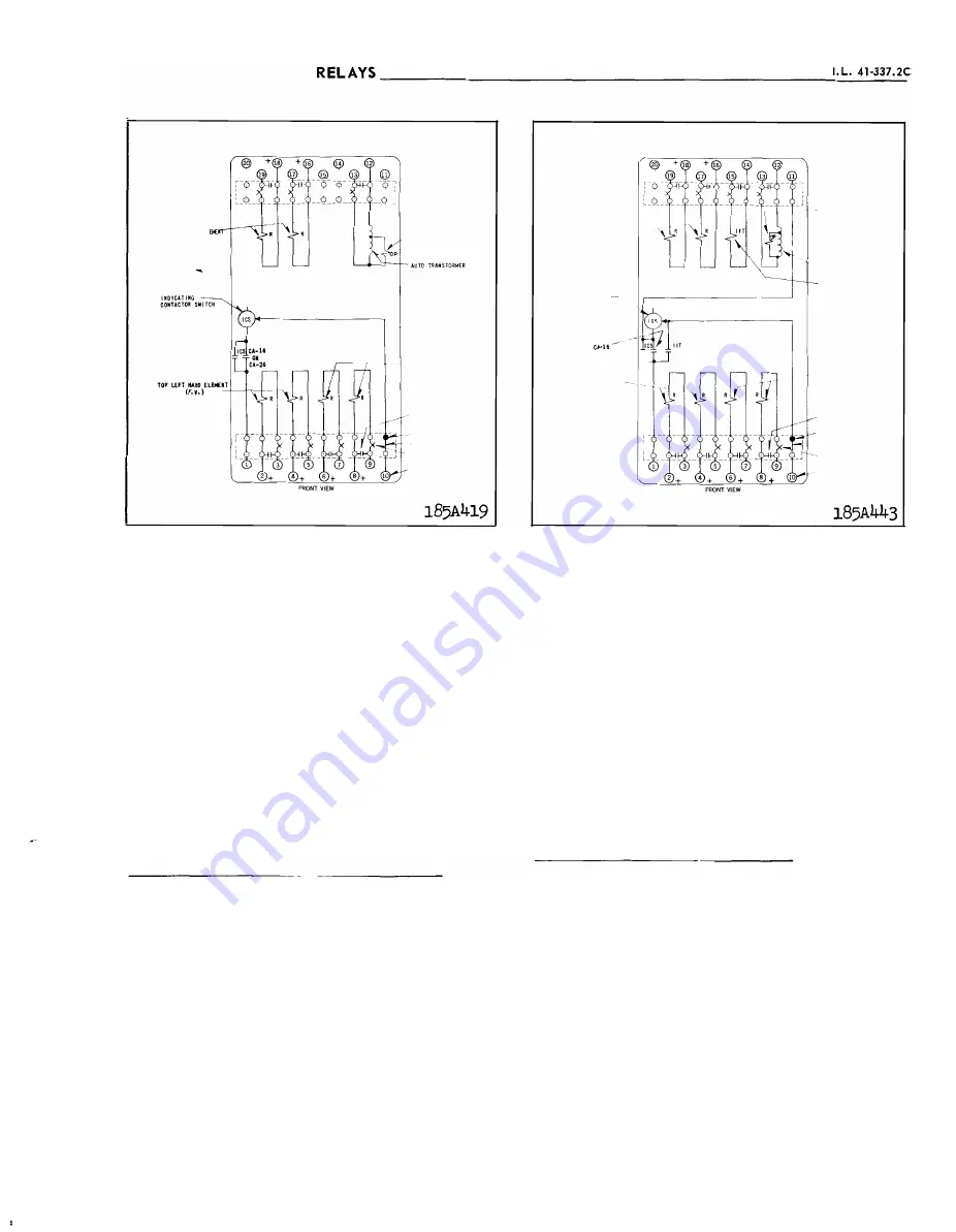
TYP ES CA- 1 6 AND CA-26
:!OTTC»4 RIGHT HANO EL
( F . V . )
IIOTE:
WITII RELATIVE IIISTU
TAMEOUS POLAR I T I E S -'S
SIIOWII. THE AMPERE
TURIIS 1 M THE PAIRED
RESTRA IIIIIIG GOILS ADD
TO PRODUCE MAXIMUM
TOll QUE .
INTERNAL SCHEMATIC
BOTlllot LEFT HAHO ELDf:IIT
( F . V . )
TaP R liKT
11
.. 0 £lEM.
( f . V . )
- CII.�SS I S OPERATED
SHORTliiG SWITCH
REO HAMOLE
- TEST SWITCH
CURREIIT TEST JACK
- TERMINAL
Fig. 3. Internal Schematic of the Type CA-1.6 B us Relay
bus. The s econdary winding of the auto-transformer,
which is a tapped section of the w inding, is con
nected to the operating element of the relay.
The operating element consists of an
"E"
type
laminated electromagnet with an auto-transformer
winding on its c enter leg. Two identical coils on the
outer legs of the laminated structure are connected
to the second ary (tapped section) of the auto-trans
former winding in a manner so that the c ombination
of all fluxes produced by the electromagnet results
in out-of-phase fluxes in the air g ap. The out- of
phase air gap fluxe s c ause a contact closing torque.
S e n s i t i v e F a u l t D e tector C i rc u i t ( w h e re u s e d )
The sensitive fault detector circuit c onsists of
an
auto-transformer and a contactor switch. The con
tactor switch is connected across the secondary
(tapped section) of the auto-transformer windin g.
The contactor switch is a small solenoid t yp e
element. A cylindrical plunger rides up and down on
a vertical guide rod in the center of the solenoid coil.
The guide rod is fastened to the stationary core ,
which in turn screws into the unit frame. A silver
disc is fastened to the moving plunger through a heli
cal spring. When the coil is energized, the plunger
BOTTOM R I GHT HAMO
--
HEMEIIT ( F. V . )
INTERNAL SCHEMATIC
I N O I CA T I M G
COMTACTOR SWITCH �"-
c��u
l_
TOP
LEFT IIAIID
ELEMEMT ( F. V . )
NOTE:
WITH RELATIVE INSTAN
TANEOUS POLAR I T I ES AS
SHOWN, THE .\MPERE
TURNS I M TttE PAIREO
RESTU I M I M G COILS
ADO TO PRODUCE NAXI
totUM TOROUE.
BOTTOM LfFT ll.liiO
ElEMENT ( F . V . )
-....., AUTOTRAMSFORMER
IMtliCATING
INSTAIITAIIEOUS
TR I J> ATTACHMENT
TOP RtUT,M.UD
ELENEMT ( F . V . )
CHASS I S OPERATED
SIIOitT IMG SWITCtt
ltEO ttiNOLE
TEST SWITCH
CURRENT TEST JACK
TERtotlllil
Fig.
4.
Internal Schematic of the Type CA-26 Transformer
Relay
moves upward c arrying the silver disc whic h bridges
three conical- shaped
stationary contacts. In this
p osition, the helic al spring is compre ssed and the
plunger is free to move while the contact remain s
stationary. Thus, a-c vibrations oL the p lunger are
prevented from c ausing contact bouncing. A Mic arta
disc is fastened to the bottom of the guide rod by
two small nuts. Its po sition determines the pick up
current of the element.
The auto-transformer is designed to saturate at
high values of current to limit the amount of curren t
to the contactor switch.
I n d i c a t i n g C on t a c t o r S w i t c h U n i t ( I C S)
The d-e indicating contactor switch is a small
clapper type device. A magnetic arm ature , to which
leaf-spring mounted contacts are attached , is at
tracted to the magnetic core upon e nergization of the
switch. When the s witch close s, the moving contacts
bridge two stationary contacts , completing the trip
circuit. Also during this operation two fingers on the
armature deflect a spring located on the front of the
switch, which allows the operation indic ator target
to drop . The target is reset from the outside of the
case by a push rod located at the bottom of the cover .
The front spring, in addition to holding the target,
3
www
. ElectricalPartManuals
. com


