T YP E S CA- 1 6 AND CA-26
IWICATIM
c•TACTOI IWITtll
lOP LEFT tMI ElB8IT
,,_,,,
won::
WITH IEI.ATIVE IIISTAit•
TAIIEOUS POUUTUI AS
IMM· litE
ANP(II:E
TUlliS
II
TilE PAllED
IIESTIA IIII&
tOILS
ADD
TO
PIODLICl MAXIMUM
TOIQU£.
UfT Mll,l .....
, ...
.
)
187A434
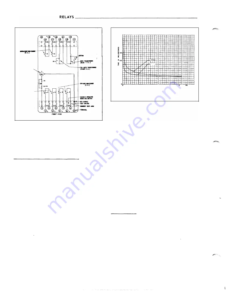
Fig.
5.
Internal Schematic of the Type CA- 1 6 B us Relay
with a Sens itive Fault Detector
provides restraint for the armature and thus controls
the pick-up value of the switch.
I n d i c at i n g I n s t a n t a n e o u s
T r i p
U n it
( l i T )
The instantaneous trip unit is a small a-c operated
cl apper type devic e . A magnetic armature, to which
leaf- spring
mounted contacts are attached , is at
tracted to the magnetic core upon energization of the
switch. When the switch clos e s , the moving contacts
bridge two stationary contacts , completing the trip
circuit . Also during this operation , two fingers on
the armature deflect a spring loc ated on the front of
the s witch which allows the operation indic ator target
to drop. The target is reset from the outside of the
case by a push rod located at the bottom of the cover.
A core screw acces sible from the top of the s witch
provides the adjustable p ick-up range.
O P E RAT I O N
The typ es CA- 16 and CA-2 6 rel ays are induction
disc relays with four electromagnets mounted on two
discs that are fastened on a common sh aft. One of
the elect romagnets is the op erating element while
the other three are restraint elements. The re straint
elements are energized from the secondaries of c ur-
4
240
200
CA-<6
i
80
a
�
40
20
40
60
80
100 120 14
OPERATING CURRENT IN
AMPERES
Curve
537956
Fig. 6. Typ ical Time Curves of the CA- 1 6 and CA-26 dif
ferential Relays
rent transformers connected to the bus , and the
operating circuit is energized in accordanc e with the
current flowing in the differential connection of the
current transformers .
A current of
5
amperes in at terminal 1 8 and out of
terminal
Hl
will produce a definite amount of re
straining torque (see Fig. 3 . ) Simil arly , a current of
5
amperes fl owing in at terminal 16 and out of ter
minal 17 will produce an e qual amount of torque . If
both of these currents flow at the same time with the
polarity as indicated above, their effect will be addi
tive and they will produce the same torque as though
10 amperes were flowing in terminal 16 and out of ter
minal 1 7. Conversely , if e qual currents flo w in these
two coils, but in opp osite directions, their ampere
turns will c ancel and no torque will be produced. The
s ame relationship applies for the p aired coils of the
other two restraining· units of the relay.
C H AR AC T E R ! S T E R I C S
CA- 1 6
Bus R e l ay
This relay has variable percentage characteristics
which means that the operating coil current required
to close the relay contacts, expressed in per cent of
the total re straint current , v arie s with the magnitude
of the re straint current. The rel ay sensitivity is high,
corresponding to a low percentage ratio , at light cur
rents, and its sensitivity i s low, corresponding to
high percentage unbalance , at high currents . The re
lay is made sensitive at l ow currents in order to de
teet light internal faults on the bus bein g protected .
At the same time , however, its reduced sensitivity at
www
. ElectricalPartManuals
. com


