T YP ES CA- 1 6 AND CA-26 R ELAY S
0
0
0
0
0
0
0
i
1
- r
0
2
4 6
8
1 0
30
'O
1 0
90
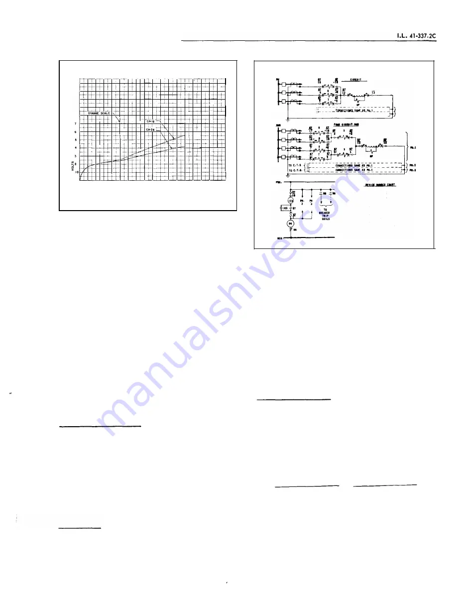
OPERATING CURRENT IN AMPERES
-+
-
Curve
537957
Fig.
7.
Typ ical Burden Characteristic of the Operating
C ircu it of the CA- 1 6 and CA-26 D ifferential R e
lays
the higher currents allows the various current trans
formers involved to depart from their true ratio to a
large extent without causing false tripping of the re
lay for external faults.
The variable percentage characteristics are par
ticularly advantageous when severe saturation of cur
rent transformers is caused by the d-e c omponent of
asymmetric al
short circuits. In the cas e of buses
located close to generating stations where the d-e
components decay slowly, the breakdown
in
ratio of
the current transformers will be much greater than
would ever be expected from a consideration of the
usual
ratio curves of the current transformers in
volved.
The time of operation of the relays is shown in
Figure
6.
C A - 2 6 T r a n sfor m e r
R e l ay
The type CA-
26
transformer differential relay in
cludes an indicating instantaneous trip unit ( se e Fig.
4) ,
which operates on internal faults. The instanta
neous unit should have a setting e qual to the maxi
mum rms symmetrical external fault current. Such a
setting will
p
revent operation of the instantaneous
unit when a current transformer is severely satur ate d
by the d-e component of an asymmetrical external
fault current.
T r i p C i r c u it
The main contacts will safely close
30
ampere s
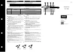
ElTEIIINAL 'SCHENUI C Of ()tiE 'SET Of TYPE CA-18 RELArs
fOR THE PROTECl'IOI Of
·A
THREE AIO fOU" CIRCUIT
IUS
I
1
TllllE
••
"
}
.... 1
ro c.r.s
Pl•l
ro e.r.s
l
::;,_
_ _ __
�E�TI�!. �-'� �·�
_ _ _ ,.,,
17
�
''fiCEIT&tE
D
lffUIITIIL IIU'
•
nft
11-ll
let ·
IIIICATIII
c•TAct• WITU
l
tr·
• .
offt.t.TIII
CIIL
IMTT•
L.l.
lu.JT)
11
I
•
,&lltD
IISTUIIT
Clll
""
(IOniM
1 •••
EWUT)
Y..ll
S
•
H.llll IISTIIIIT
Clll
nUt
(Ttp
L·•· IWIIIT)
T
•
.PUIII
IIITUIIl
UIL
(TIP
1.1.
ILiiiiiT)
M•
&lllli&IY TIIPtlll IIUY,
TYfl. II.
187A424
Fig.
8.
External Schemat ic of the Type CA- 1 6 Relays for
Three and Four Circu it Bus Protection
at
2 50
volts d-e and the seal-in contacts of the in
dicating contactor switch will s afely car ry this c ur
rent long enough to trip a circuit breaker.
The indicating instantaneous trip contacts will
safely close
30
amperes at
250
volts d-e, and will
c arry this current long enough to trip bre aker.
The indic ating contactor switch has two taps that
provide a pick- up setting of
0 . 2
or
2
amperes . To
change taps requires connecting the lead located in
front of the tap block to the desired setting by means
of a screw connection.
T r i p C i rc u i t C o n s ta n ts
Indicating Contactor Switc h (ICS)
0.
2
ampere tap
6 . 5
ohms d-e resistance
2.0
ampere tap
0. 15
ohms d-e resistance
E N E R G Y R E Q U I R EM E N T S
Burden of each restraint coil at
5
amperes
VOLT AMP ERES
POWER FACTOR
.
75
. 7
Continuous Rating
14
amperes
1
second rating
4 60
amp eres
5
www
. ElectricalPartManuals
. com


